
How to Install a Conversion Kit on a Ram 1500
Advantages of Monroe® Suspension Conversion Kit
Designed to convert a vehicle’s factory-equipped air suspension to a conventional suspension, a Monroe suspension conversion kit restores factory ride height and delivers a stable, comfortable ride. Your vehicle will ride and handle the same way that a vehicle with a conventional suspension system performs.
For hardworking 2013-2018 Ram 1500 half-ton trucks, a conversion kit is a cost-effective alternative to replacing the OE air suspension system. Every Monroe conversion kit features premium-quality replacement components including application-tuned shock/strut, coil spring(s) and necessary mounting hardware – needed for a complete bolt-on worry-free solution. Check out this ServiceGram to learn more about the advantages of a Monroe conversion kit for the Ram 1500.
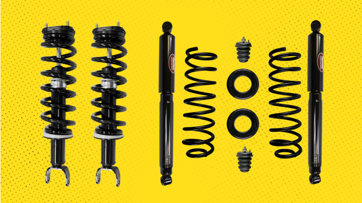
For a complete four-corner repair, be sure to purchase these three Monroe part numbers: 90028C1 (front right strut assembly), 90028C2 (front left assembly), and 90028C3 (rear coil springs, shock absorbers, spring isolators, jounce bumpers). Check out the steps for installing a Monroe suspension conversion kit on a Ram 1500 truck.
Steps for Converting an Air Suspension to a Conventional Suspension

1. Follow the deflation procedure outlined in the service manual.

2. Raise vehicle at proper lift points to make sure the vehicle is properly supported.

3. Remove the front wheel.

4. Support the vehicle with a jack stand.

5. Remove the outer tie rod end.

6. Disconnect upper ride height sensor arm from the upper control arm.

7. Remove ride height sensor and bracket assembly from the frame.

8. Disconnect the ride height sensor connector.

9. Protect connector with electrical tape or polybag and use a zip tie to secure it to the frame.

10. Remove the upper anti-sway bar end link nut, cushion and retainer.

11. Remove the lower strut mounting bolt and save for reuse.

12. Remove the three upper strut assembly mounting nuts.

13. Disconnect the air fitting from the top of the strut assembly using an open-ended wrench.

14. Protect air line with electrical tape or place in polybag and use a zip tie to secure it to the frame.

15. If necessary, remove the lower control arm support to aid in removing the strut assembly.

16. Remove the air strut assembly.

17. Install the new strut assembly.

18. Loosely install the three upper strut assembly mounting nuts.

19. Loosely install the lower strut mounting bolt using the original hardware.

20. Reinstall the upper ball joint to the spindle assembly and torque to 40-foot pounds (54 N-M) and then an additional 200 degrees.

21. Reinstall the outer tie rod end and torque to 22-foot pounds (30 N-M) and then an additional 90 degrees.

22. Loosely install the upper anti-sway bar end link, retainer, cushion and nut.

23. Reinstall the front wheel and hand tighten the lug nuts.

24. Safely lower the vehicle to the ground and torque the wheel to 140-foot pounds (190 N-M) for flanged lug nuts and 130-foot pounds (176 N-M) for cone lug nuts.

25. Torque the three upper strut assembly mounting nuts to 45-foot pounds (61 N-M).

26. Torque the lower strut mounting bolt to 155-foot pounds (210 N-M).

27. Torque the upper anti-sway bar end link to 16-foot pounds (22 N-M).

28. Repeat the steps on the other side of the vehicle.

1. Raise vehicle by frame at proper lift points and make sure the vehicle is properly supported.

2. Support the rear axle and remove the rear wheel.

3. Remove the air spring by disengaging the three clips, one at a time, on top of the air spring.

4. Disconnect the air fitting from the top of the air spring using an open-ended wrench. Remove the air spring.

5. Disconnect lower and upper end of the rear anti-sway bar link. Save hardware for reuse.

6. Remove the bolt holding the brake hose and wheel speed sensor cables to the frame. Save hardware for reuse.

7. Remove the rear wheel housing splash shield.

8. Disconnect rear ride height sensor arm.

9. Disconnect the ride height sensor connector.

10. Remove the ride height sensor and bracket from the frame.

11. Protect connectors with electrical tape or polybag and use a zip tie to secure it to the frame.

1. Support the vehicle under the frame.

2. Remove the jounce bumper extensions by cutting the welds at the bracket. Use caution to not cut into the bracket.

3. Make a mark on the brackets 1" (25.4mm) from the centerline of the hole (any direction).

4. Drill a 5/16" (8mm) hole. This hole is needed for the tab on the new jounce bumper.

5. Test fit the bumper to ensure the hole placement and diameter are correct.

6. Paint the bracket to prevent any corrosion.

7. Once the paint is dry, install the new jounce bumper and orient so that the tab fits into the drilled hole. Torque the jounce bumper nut to 24-foot pounds (32 N-M).

1. Remove the lower bolt of the rear shock absorber.

2. Remove the upper bolt of the rear shock absorber. Note: A modified 21mm wrench may be needed to access the upper shock absorber nut for the mounting bolt.

3. Remove the shock.

4. Protect the air spring air line with electrical tape or polybag and use a zip tie to secure it to the frame.

5. Install the coil spring and rubber spring isolator onto the axle with the larger diameter coil facing up. The rubber spring isolator needs to be placed at the top end of the spring.

6. Raise rear axle enough to ensure the upper coil remains properly seated in the upper spring seat.

7. Loosely install the upper bolt of the rear shock absorber using the original hardware.

8. Loosely install the lower bolt of the rear shock absorber using the original hardware.

9. Loosely install the rear anti-sway bar end link reusing the original hardware.

10. Reinstall the bolt holding the brake hose and wheel speed sensor cables to the frame.

11. Repeat steps on the other side of the vehicle.

12. Reinstall the rear wheel. Hand tighten the lug nuts.

13. Safely lower the vehicle to the ground and torque the lug nuts to 140-foot pounds (190 N-M) for flanged lug nuts. Torque the wheel to 130-foot pounds (176 N-M) for cone lug nuts.

14. Torque the upper and lower shock mounting hardware to 100-foot pounds (135 N-M). Torque the upper anti-sway bar end link nut to 79-foot pounds (107 N-M).

15. Reinstall the rear wheel housing splash shield.

1. Disconnect the negative lead on the battery.

2. Locate the fuse box on the driver’s side of the engine compartment.

3. Remove the K03 air suspension relay.

4. Remove the F05 air suspension comp 40A fuse.

5. Remove the F50 air suspension mod 20A fuse.

6. Reconnect the negative lead of the battery.
Learn more about quality suspension parts, find the right car part, or find a local repair shop today.
The content contained in this article is for informational purposes only and should not be used in lieu of seeking professional advice from a certified technician or mechanic. We encourage you to consult with a certified technician or mechanic if you have specific questions or concerns relating to any of the topics covered herein. Under no circumstances will we be liable for any loss or damage caused by your reliance on any content.