
How to Install a Suspension Conversion Kit on 2011-2015 Jeep Grand Cherokee with Quadra-lift suspension
Benefits of a Monroe® Suspension Conversion Kit
For 2011-2015 Jeep Grand Cherokee SUVs equipped with a Quadra-Lift air suspension system, a Monroe suspension conversion kit converts the factory electronic suspension system to a conventional suspension. Designed to restore factory ride height and deliver a stable ride, your vehicle will ride and handle the same way that a vehicle with a conventional suspension system performs.
For 2011-2015 Jeep Grand Cherokee SUVs, a conversion kit is a cost-effective alternative to replacing the OE air suspension system. Featuring everything needed for a complete bolt-on repair, every Monroe conversion kit features premium replacement components including an application-tuned shock/strut, coil spring(s) and necessary mounting hardware.
For a complete four-corner repair, be sure to purchase these three Monroe part numbers: 90032C1 (front right assembly), 90032C2 (front left assembly), and 90032C3 (rear). This kit replaces the front air strut assemblies, rear shock absorbers and rear air springs with front passive strut assemblies, conventional shock absorbers and coil springs.
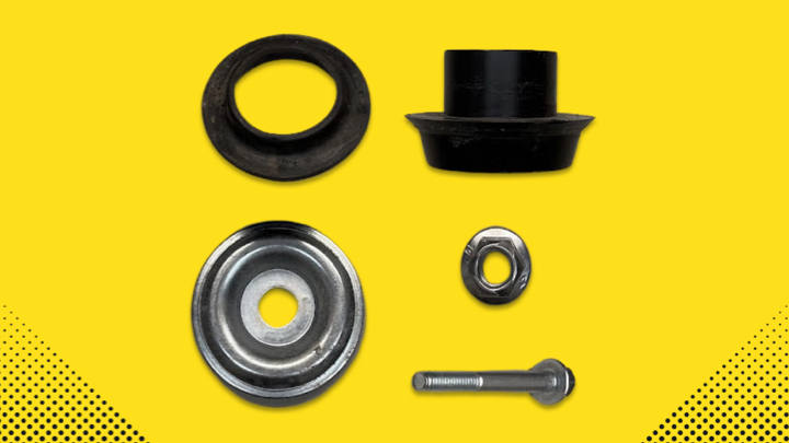
The kit contains:
· Two front strut assemblies
· Two rear coil springs
· Two rear shock absorbers
· Two rear upper coil spring isolators
· Two front upper coil spring isolators
· Two rear lower coil spring centering pucks & hardware
· Instruction sheet
Check out the steps for installing a Monroe suspension conversion kit on a Jeep Grand Cherokee.
Steps for Converting a Quadra-Lift Air Suspension to a Conventional Suspension
Before You Start:
· Monroe part numbers required for a complete repair: 90032C1, 90032C2 and 90032C3 (each part number sold separately).
· Read these instructions and any instructions printed on the parts package carefully PRIOR to removing the components from the vehicle.
· Part number on shock or spring may differ from part number on the carton. The contents are correct for the vehicle.
· For questions or concerns, contact Gurus On-Call at 1-800-325-8886.
WARNING – Safety Steps:
· If the shocks supplied are nitrogen gas pressurized, do not heat or open.
· Always wear safety glasses for eye protection.
· Use safety stands whenever a procedure requires you to be under a vehicle.
· Before servicing any electrical component, ensure that the ignition is off, the key is out of the ignition and the negative lead is disconnected from the battery. Refer to the owner’s manual for the correct procedure.
1. Remove the appropriate fuse(s) based on the model year of the vehicle. Reference the fuse box panel for locations of fuses and relay.
· 2011-2013 – Remove J1 fuse (air suspension)
· 2014-2015 – Remove F50 fuse (air suspension control module); F5 fuse (compressor for air suspension - if equipped); K3 relay (air suspensinon relay)
2. Using a 12mm wrench, slowly loosen airline fitting from the top of the strut assembly letting air bleed from the airline and air spring. Repeat on the other side of the vehicle.
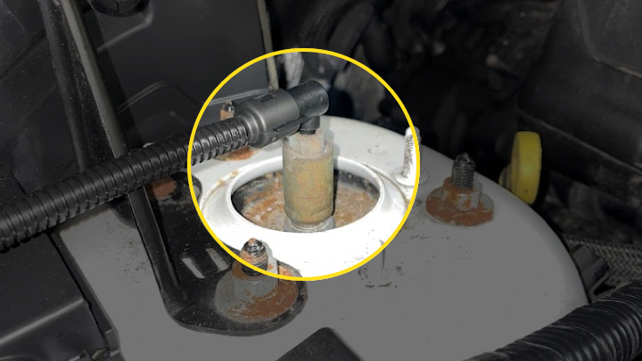
3. Disconnect the airline from the air suspension strut assembly. Find a safe place to zip tie airline out of the way.
4. Repeat steps 2-3 on the other side of the vehicle.
5. Raise the vehicle by the frame at proper lift points and make sure the vehicle is properly supported. Refer to the owner’s manual for the correct lifting procedure.
6. Remove the wheels.
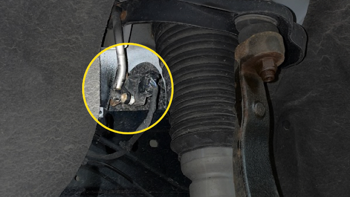
7. Disconnect the lower end of ride height sensor link.
8. Remove half shaft. NOTE: For details of half shaft removal, refer to OE service manual. There are many steps for removal.
9. Carefully remove the three upper mounting nuts of the strut assembly.
10. Remove the strut assembly from vehicle.
11. Repeat steps 5-10 on the other side of the vehicle.
1. Position the strut assembly to the vehicle aligning the upper mounting studs into the body.
2. Loosely install the upper mounting nuts. These will need to be torqued properly at a later step.
3. Install the half shaft.
4. Install strut assembly lower clevis on the lower control arm. Install the bolt and nut. Tighten to173-lbft (235 N·m).
5. Install upper ball joint into the knuckle. Install the upper ball joint retaining nut. Tighten to 70 ob-ft (95 N·m).
6. Install tie rod end on the knuckle. Tighten the nut to 70 lb-ft (95 N·m).
7. Install stabilizer link on the lower control arm. Tighten the stabilizer link upper nut to 85 lb-ft (115 N·m).
8. Reinstall the brake caliper.
9. Install the wheel speed sensor. Tighten the bolt to 95 lb-in (10.7 N·m).
10. Per manufacturer recommendations, install a NEW half shaft hub/bearing nut. Tighten to 229 lb-ft (310 N·m).
11. Reconnect the ride height sensor.
12. Repeat 1-11 on the other side of the vehicle.
1. Using a 12mm wrench, SLOWLY loosen airline fitting from the top of the air spring letting air bleed from the airline and air spring. Repeat on the other side of the vehicle.
2. Disconnect the airline from the air spring. Find a safe place to zip tie airline out of the way.
3. Disconnect the lower end of the ride height sensor link. Refer to the photo in Step 7 of the Front Strut Assembly Removal Procedure.
4. To remove the air spring, push down to compress, tilt the top out and lift the air spring from the lower control arm.
5. Repeat steps 1-4 on the other side of the vehicle.
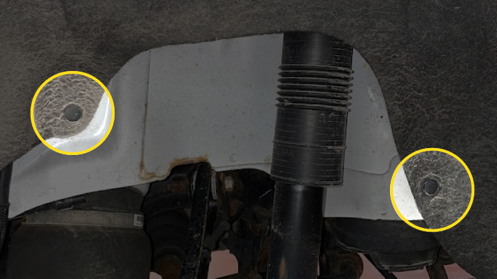
1. Remove the two wheel well push pins.
2. Remove the upper shock bolt; retain for use with the new shock.
3. Remove the lower shock bolt and nut; retain for use with the new shock.
4. Remove the shock from the vehicle.
5. To install coil springs, the following procedures may need to be completed to allow adequate space to install the coil spring. Refer to the manufacturer service manual for more information and images.
· Remove the brake caliper.
· While supporting the outer end of the lower control arm, remove the tension kink to knuckle nut and bolt.
· Remove the wheel speed sensor bolt and remove sensor.
· Remove the camber link to knuckle bolt/nut.
· Remove the stabilizer link to the lower control arm nut.
· Remove the toe link to the knuckle nut and bolt.
· Remove the half shaft from the hub.
6. Install the coil spring centering puck, lower spring isolator and hardware that is provided in the kit. The bolt, coil spring isolator and centering puck should be installed on the top of the lower control arm. The large washer and nut will be installed underneath the lower control arm.
7. Place the upper spring isolator provided in the kit on the spring.
8. Position the spring on the centering puck in the lower control arm.
9. While holding the spring in position, carefully raise the lower control arm with a support fixture to normal ride height.
10. If previously removed, install the axle through the hub/bearing. Per manufacturer recommendations, install a NEW half shaft nut and tighten to 229 lb-ft (310 N·m).
11. If previously removed, position the toe link and install the nut. Tighten to 79 lb-ft (108 N·m).
12. Position the new shock so that the upper shock bolts can be installed. Install the upper shock bolts. Tighten to 173 lb-ft (235 N·m).
13. Install the shock lower bolt and nut. Tighten to 173 lb-ft (235 N·m).
14. If previously removed, install the stabilizer link to the lower control arm nut. Tighten to 81 lb-ft (110 N·m).
15. If previously removed, install the camber link to the knuckle bolt. Tighten to 81 lb-ft (110 N·m).
16. Install the wheel speed sensor and retaining bolt. Tighten to 95 lb-in (10.7 N·m).
17. Reinstall the brake caliper.
1. If previously removed, reinstall all wheel well splash shields.
2. Reinstall the wheels and hand tighten the lug nuts. Safely lower the vehicle to the ground and torque the lug nuts to 130 lb-ft (176 N·m).
3. Torque three upper front strut assembly mounting nuts to 21 lbs-ft (28 N·m). Do this for both front strut assemblies.
NOTE: If a Service Suspension message appears on the instrument cluster when starting the vehicle, a scan tool will be needed to clear the message. Once cleared, the service message shouldn’t reappear.
Learn more about quality Shocks, Structs, & Strut Assemblies , find the right car part, or find a local repair shop today.
The content contained in this article is for informational purposes only and should not be used in lieu of seeking professional advice from a certified technician or mechanic. We encourage you to consult with a certified technician or mechanic if you have specific questions or concerns relating to any of the topics covered herein. Under no circumstances will we be liable for any loss or damage caused by your reliance on any content.