
How to Install a Suspension Conversion Kit on Full-Size Chevrolet/GMC SUVs
Advantages of a Monroe® Full Size SUV Suspension Conversion Kit
For full-size General Motors SUVs equipped with magnetic ride control and an air leveling suspension system, a Monroe suspension conversion kit converts the factory electronic suspension system to a conventional suspension. Designed to restore factory ride height and deliver a stable ride, your vehicle will ride and handle the same way that a vehicle with a conventional suspension system performs.
For 2015-2020 Chevrolet and GMC full-size SUVs, a conversion kit is a cost-effective alternative to replacing the OE magnetic ride control suspension system. Featuring everything needed for a complete bolt-on repair, every Monroe suspension conversion kit features premium replacement components including an application-tuned shock/strut, coil spring(s) and necessary mounting hardware. This applies to 2015-2020 vehicles including the Chevrolet Suburban & Tahoe LTZ; GMC Yukon & Yukon XL; and Cadillac Escalade & Escalade ESV.
For a complete four-corner repair, be sure to purchase these three Monroe part numbers: 90031C1 (front right assembly), 90031C2 (front left assembly), and 90031C3 (rear). This kit replaces the front magnetic ride control struts, rear magnetic ride control shocks and rear coil springs with front passive strut assemblies, rear conventional shock absorbers and coil springs. The kit contains:
· Two front strut assemblies
· Two rear coil springs
· Two rear shock absorbers
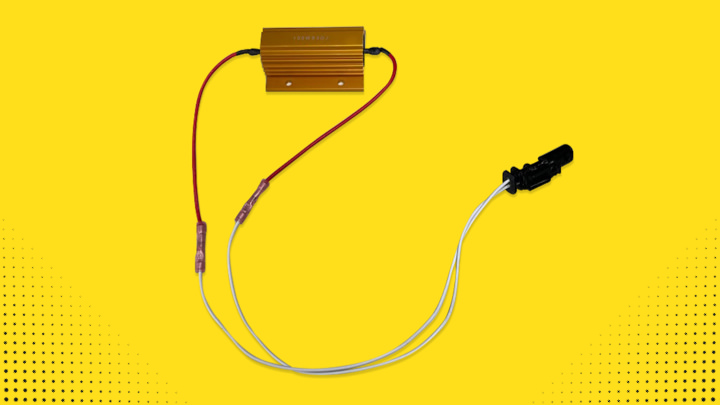
· Four shock actuator simulators
· Zip ties
· Instruction sheet
Check out the steps for installing a Monroe suspension conversion kit on a Chevrolet or GMC full-size SUV.
Steps for Converting a Magnetic Ride Control Suspension to a Conventional Suspension on GM Full-Size SUVs
Before You Start:
· Monroe part numbers required for a complete repair: 90031C1, 90031C2 and 90031C3 (each part number sold separately).
· Read these instructions and any instructions printed on the parts package carefully PRIOR to removing the components from the vehicle.
· Part number on shock or spring may differ from part number on the carton. The contents are correct for the vehicle.
· For questions or concerns, contact Gurus On-Call at 1-800-325-8886.
WARNING – Safety Steps:
· If the shocks supplied are nitrogen gas pressurized, do not heat or open.
· Always wear safety glasses for eye protection.
· Use safety stands whenever a procedure requires you to be under a vehicle.
· Before servicing any electrical component, ensure that the ignition is off, the key is out of the ignition and the negative lead is disconnected from the battery. Refer to the owner’s manual for the correct procedure.
1. Raise the vehicle by the frame at proper lift points and make sure the vehicle is properly supported. Refer to the owner’s manual for the correct lifting procedure.
2. Remove the wheel.
3. Remove the wheel housing splash shield.
4. Support the front lower control arm.
5. Disconnect the electrical connector from the strut assembly.
6. Remove the lower strut assembly mounting bolts.
7. Remove the three upper strut assembly mounting bolts.
8. Carefully remove the strut assembly from the vehicle. Note: Retain strut assembly. Electrical connector will be needed for a later step.
9. Install the new strut assembly.
10. Install the three upper strut assembly mounting nuts. Hand tighten only.
11. Repeat the steps on the other side of the vehicle.
1. Support the rear axle assembly with the proper jack stand. Refer to owner’s manual for proper lifting procedure.
2. Disconnect the electronic suspension control connector.
3. Disconnect the airline fitting.
4. Remove the lower shock bolt and nut. Save hardware for reuse.
5. Remove the upper shock absorber bolt and nut. Save hardware for reuse.
6. Remove the shock absorber from vehicle. Note: Retain shock absorber. Electrical connector will be needed for a later step.
7. Repeat the steps on the other side of the vehicle.
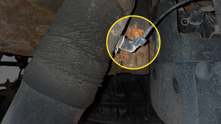
8. Disconnect rear ride height sensor arm.
9. Disconnect the ride height sensor connector.
10. Remove the ride height sensor and bracket from the frame.
11. Protect connectors with electrical tape or polybag and use a zip tie to secure it to the frame.
1. Continue to support the rear axle assembly with the proper jack stand.
2. Remove the stabilizer shaft link retaining the nut from the frame.
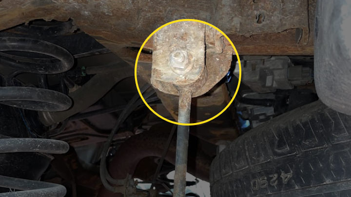
3. Remove the rear brake hose bracket bolt at the rear axle.
4. Repeat steps 1-3 on the other side of the vehicle.
5. Lower the rear axle until the coil springs are fully unloaded.
6. Remove the coil springs and spring isolators. Evaluate the spring isolators and either use new OE spring isolators or save the existing spring isolators for reuse.
1. Position the shock absorber and install the upper shock absorber bolt and nut. Hand tighten only.
2. Install the coil spring and spring isolator. Ensure orientation of the spring pig tail is properly seated in the spring seat.
3. Repeat steps 1-2 on the other side of the vehicle.
4. Raise the rear axle so that the lower shock absorber bolts and nuts can be installed.
5. Install the lower shock absorber bolts and nuts on both shock absorbers. Hand tighten only.
6. Install both rear brake hose bracket bolts at the rear axle. Tighten to 18 lb-ft (25 N·m)
7. Install both stabilizer shaft links to the frame. Tighten to 48 lb-ft (65 N·m) plus 40 degrees.
8. Carefully remove the jack stand that is supporting the rear axle.
Note: This procedure MUST BE completed so the air compressor doesn’t continually run. Failure to complete this procedure will cause the compressor to run continually and illuminate a service suspension message on the instrument cluster.
1. Locate the airline tee fitting fastened to the outside of the compressor mounting bracket. This is located on the driver’s side behind the rear quarter panel below the gas cap.
2. Locate the airline tee fitting fastened to the outside of the compressor mounting bracket. This is located on the driver’s side behind the rear quarter panel below the gas cap.
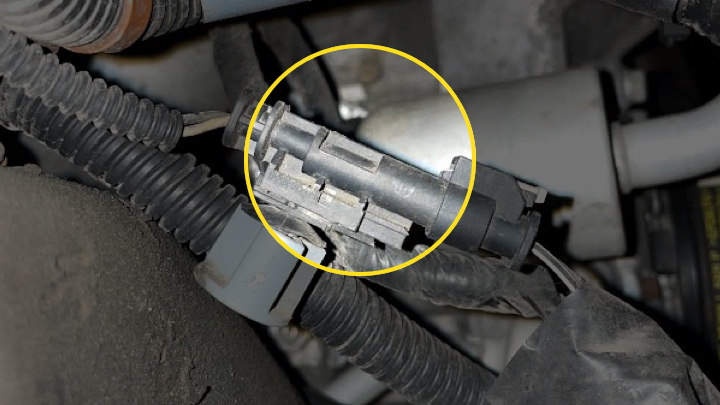
3. Unplug the line labeled Passenger Shock.
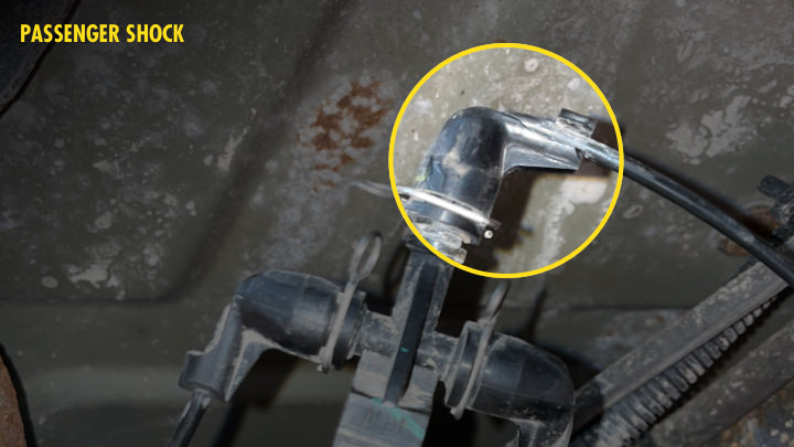
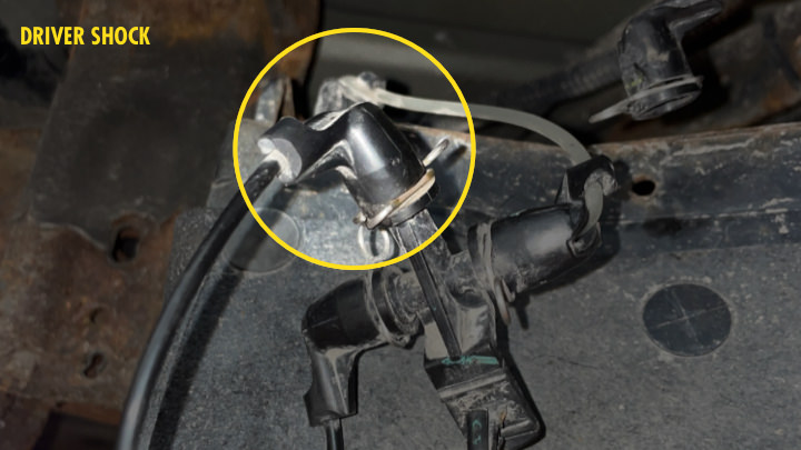
4. Locate the airline fitting that was plugged into the original driver's side air shock labeled Driver Shock in the image below. Plug this fitting on the Passenger Shock male port that was unplugged in Step 3. This creates a loop and keeps the air compressor from continually running by giving it a constant pressure reading.
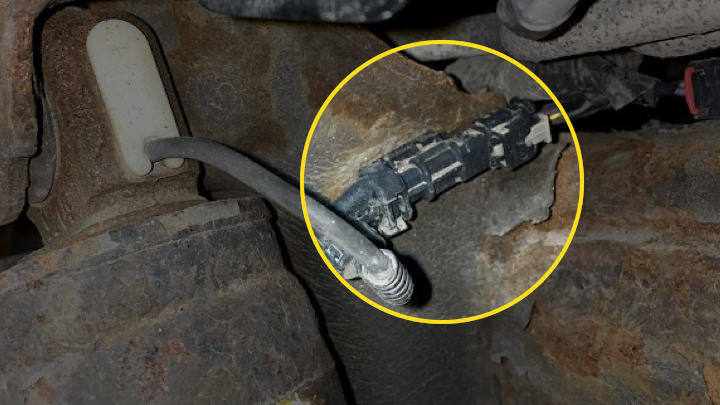
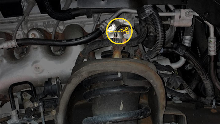
1. Cut the front strut electrical plug wires on both OE strut assemblies that were previously removed from the vehicle. Cut as shown in the photo below. Retain plugs and properly dispose of the struts.
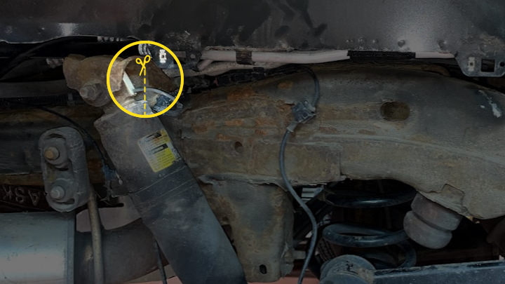
2. Cut rear air shock electrical plug wires on both OE shocks that were previously removed from the vehicle. Cut as shown in the photo below. Retain plugs and properly dispose of the air shocks.
3. Strip the wires that were cut from the struts/shocks back approximately 3/16". This will expose two wires.
4. Using the butt connectors provided in the kit, install and crimp one of the wires from the vehicle plug and one of the wires from the provided shock simulator. Repeat for other wire on the vehicle plug and shock simulator. Each wire should now be separated to not allow cross connection. Note: Electrical plug in the photo may not be the same; photo is for representation only.
1. Reinstall wheels and hand tighten the lug nuts. Safely lower the vehicle to the ground and torque the lug nuts to 140 lb-ft (190 N·m).
2. Torque three upper front strut assembly mounting nuts to 37 lb-ft (50 N·m). Do this for both front strut assemblies.
3. Torque both lower strut assembly mounting bolts to 37 lb-ft (50 N·m).
4. Torque both upper shock absorber bolts and nuts to 85 lb-ft (115 N·m).
5. Torque both lower shock absorber bolts and nuts to 85 lb-ft (115 N·m).
6. Reinstall wheel housing splash shields.
NOTE: If a Service Suspension message appears on the instrument cluster when starting the vehicle, a scan tool will be needed to clear the message. Once cleared, the service message shouldn’t reappear.
Learn more about quality suspension parts, find the right car part, or find a local repair shop today.
The content contained in this article is for informational purposes only and should not be used in lieu of seeking professional advice from a certified technician or mechanic. We encourage you to consult with a certified technician or mechanic if you have specific questions or concerns relating to any of the topics covered herein. Under no circumstances will we be liable for any loss or damage caused by your reliance on any content.