For Vehicles:
- 2008-2004 Chrysler Pacifica
- Read this instruction sheet and any instructions printed on the parts package carefully prior to removing the components from the vehicle.
- Part number on shock or spring may differ from part number on carton. The contents are correct for the vehicle.
- For questions or concerns, contact the Monroe Technical Resource Center at 734-384-7809.
WARNING!
- If the shocks supplied are nitrogen gas pressurized, do not heat or open.
- Always wear safety glasses for eye protection.
- Use safety stands whenever a procedure requires you to be under a vehicle.
- Before servicing any electrical component ensure the key is out of the ignition, ignition is off and the negative lead is disconnected from the battery. Refer to the owner’s manual for the correct procedure.
This kit replaces the rear self-leveling Nivomat shocks and springs on vehicles listed above, replacing them with heavy duty coil springs and conventional shocks. The components in this kit are designed to replace the worn or non-operational original equipment components.
- Two heavy duty coil springs.
- Two premium shock absorbers.
- Two shock absorber mounting kits.
- Instruction sheet (FORM01222).
The original ride heights of these vehicles may vary with age, mileage, and options. Measure and record existing height; this is measured from center of the wheel to the bottom of the fender well opening lip. The ride height could be considerably higher or lower if the Nivomat shocks are not functioning properly. After kit installation, the ride height may be equal to or exceed factory measurements, but will settle to factory specification after several days. Keep in mind a new coil spring may sit higher than the OE spring.
- Raise vehicle by frame at proper lift points. Consult Chrysler Owner Manual if necessary and make sure the vehicle is properly supported.
- Remove the wheel lug nuts and wheels on both sides of the vehicle.
- Support the rear axle with floor jack or adjustable stands (see photos below).
- Remove the shock absorber upper mounting bolts. Save hardware for reuse.
- Remove the lower shock absorber mounting hardware. Save hardware for reuse.
- Support crossmember on repair side with floor jack or adjustable stand.
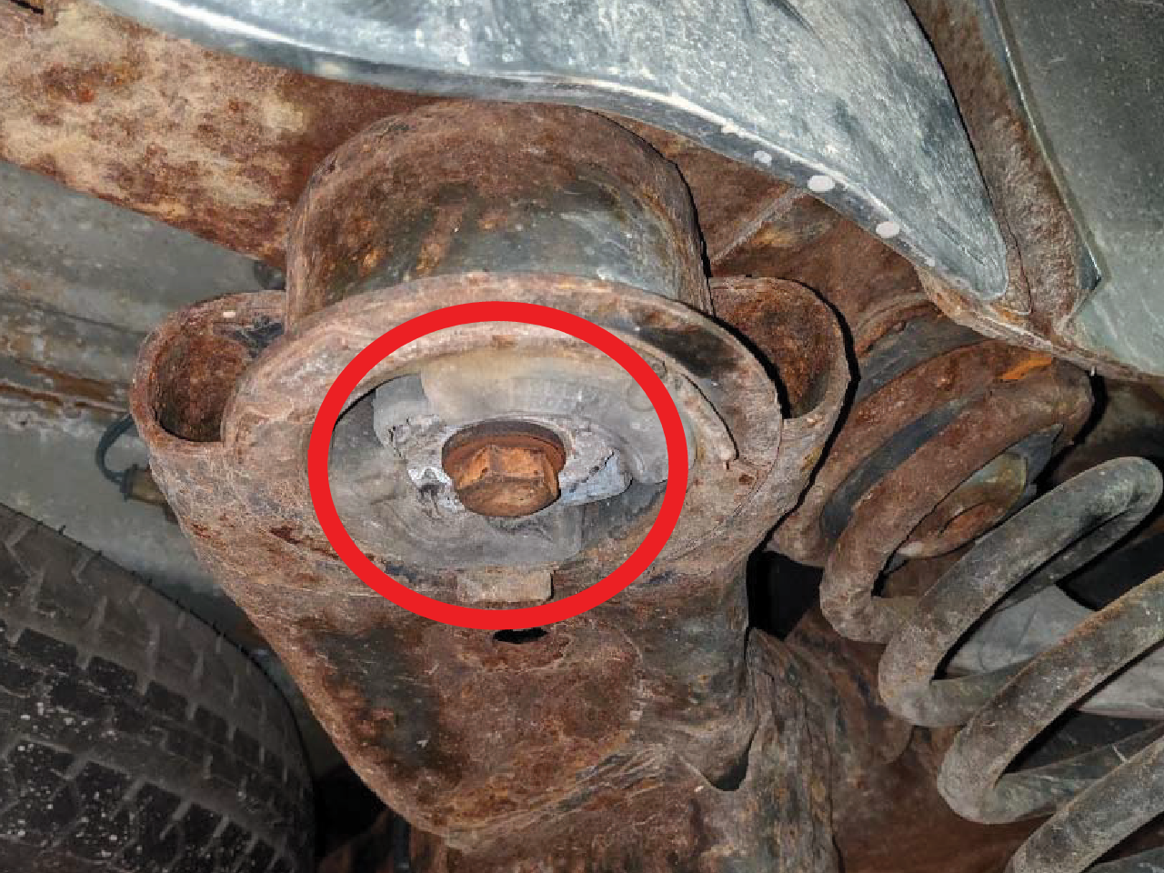
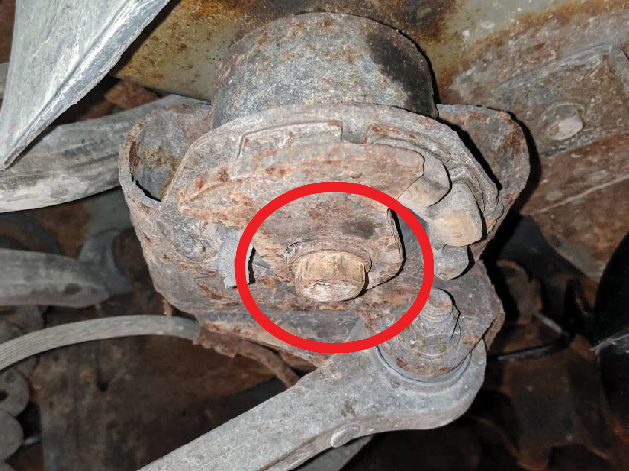
- Remove both front and rear crossmember mounting bolts on repair side of vehicle only (see photos below). Save hardware for reuse.
- Using the floor jack or adjustable stands, slowly lower the axle and crossmember on repair side down to remove the shock and coil spring. You may have to lower the axle further to install the new coil springs.
- Remove shock absorber and coil spring.
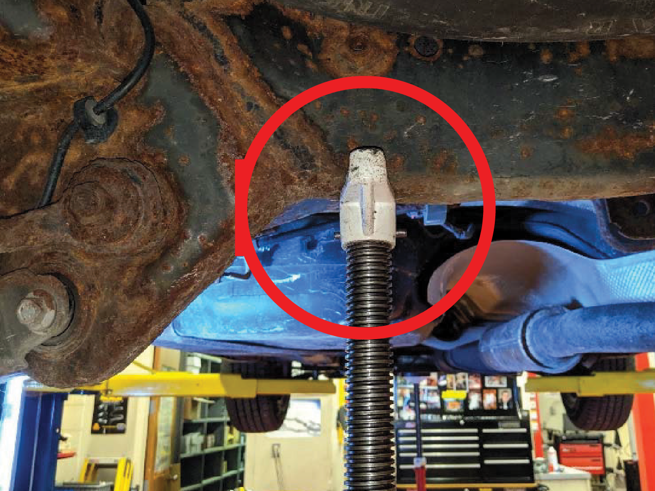
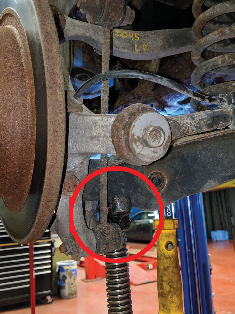
Caution: When removing crossmember mounting bolts, do not remove or loosen crossmember mounting bolts on the opposite side of the vehicle. Removing or loosening crossmember mounting bolts on both sides of the vehicle will require a rear wheel alignment following reinstallation.
- Install new coil spring, reusing the OE upper spring isolator (replace if necessary). Orient the coil spring so that the end with the tighter coil is at the top (see photos below).
- Carefully raise the rear axle and crossmember while ensuring the spring remains properly seated in the upper and lower spring seats/isolator.
- Reinstall crossmember mounting bolts and torque to 120 lb.-ft. (163 N·m). (Inspect and replace if necessary).
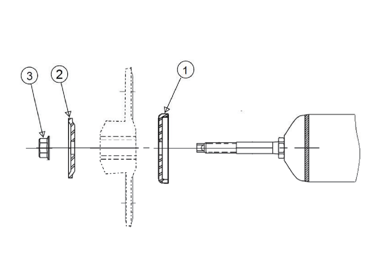
- Assemble shock mounting kit 905969 onto new shock following the diagram below. Tighten nut (3) to 20 lb.-ft. (27 N·m). Discard extra retainers.
- Install new shocks into the upper mounting holes reusing the original mounting hardware (inspect and replace if necessary). Torque upper mounting bolts to 45 lb.-ft. (61 N·m).
- Reinstall lower shock mounting hardware (inspect and replace if necessary). Hand tighten only. If necessary, raise the lower control arm with an adjustable stand or jack to align the lower mounting holes.
- Carefully remove the jacks from under the rear axle and crossmember.
- Reinstall the rear wheels and hand tighten the lug nuts. Safely lower the vehicle and torque the wheel lug nuts to 100 lb-ft (135 N·m).
- Position vehicle on alignment rack or drive-on lift. Raise lift to access lower mounting bolt. Tighten shock absorber lower mounting bolt nut to 75 ft. lbs. (102 N·m).
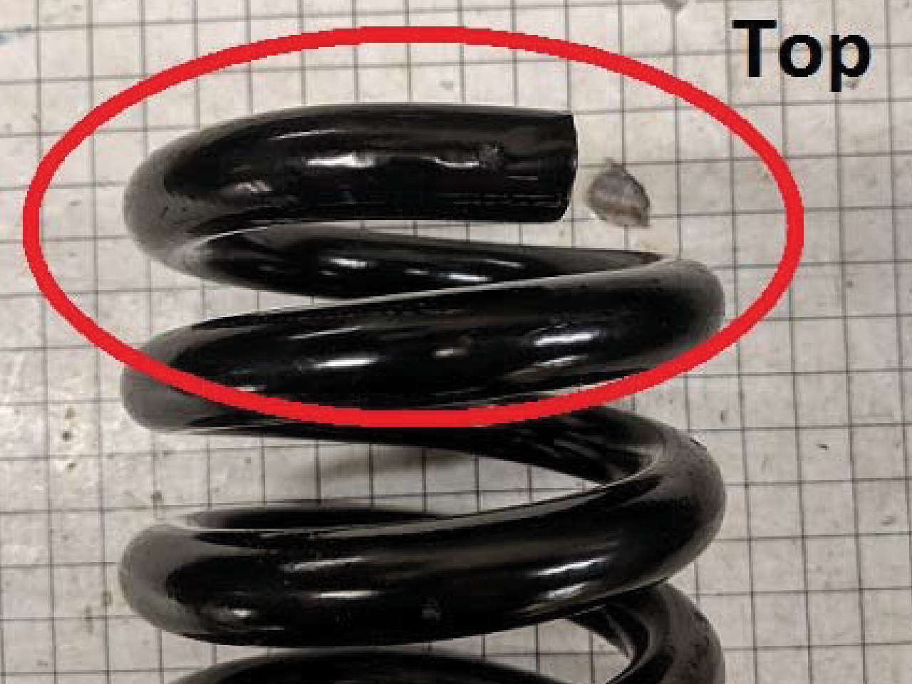
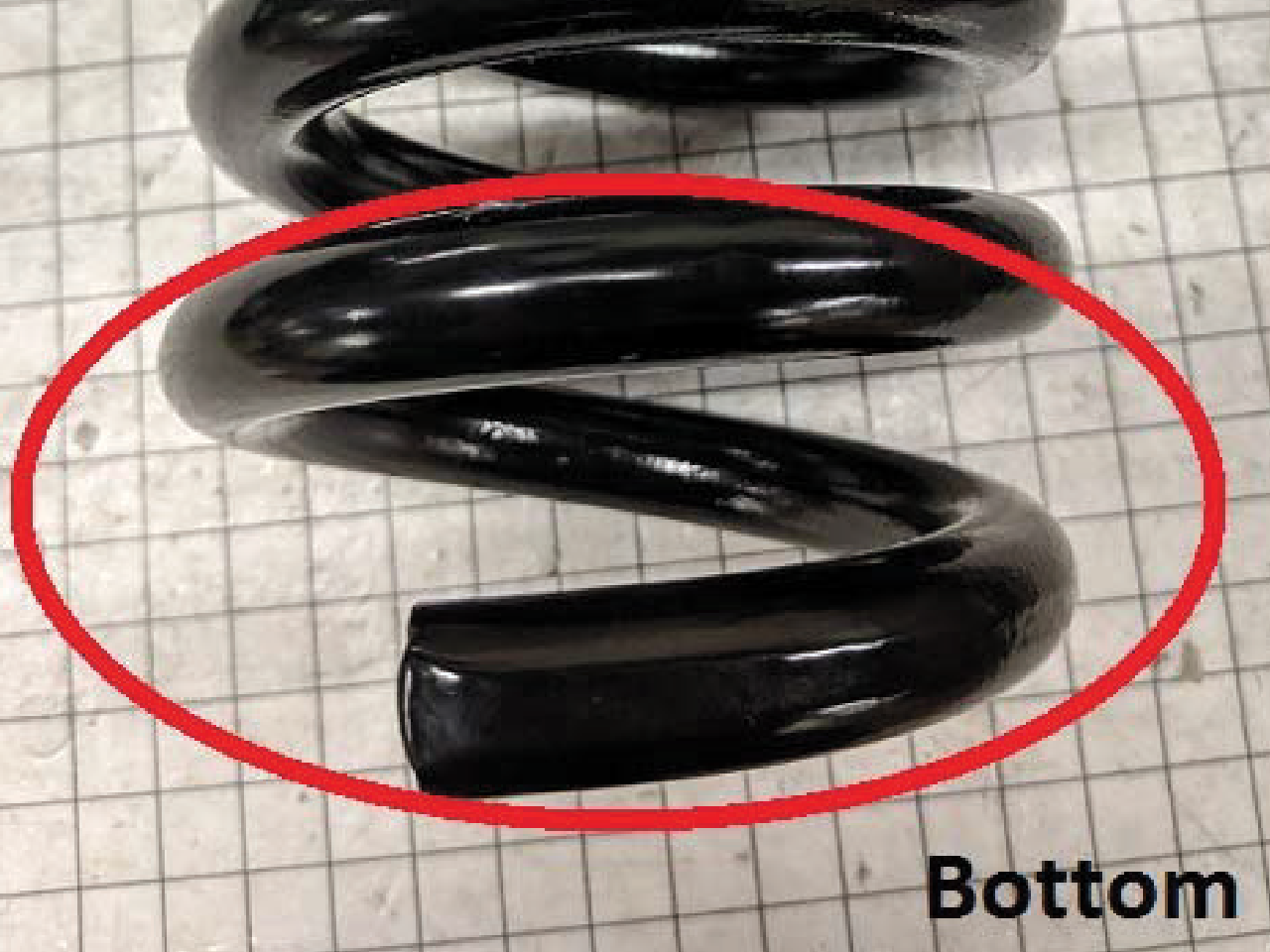
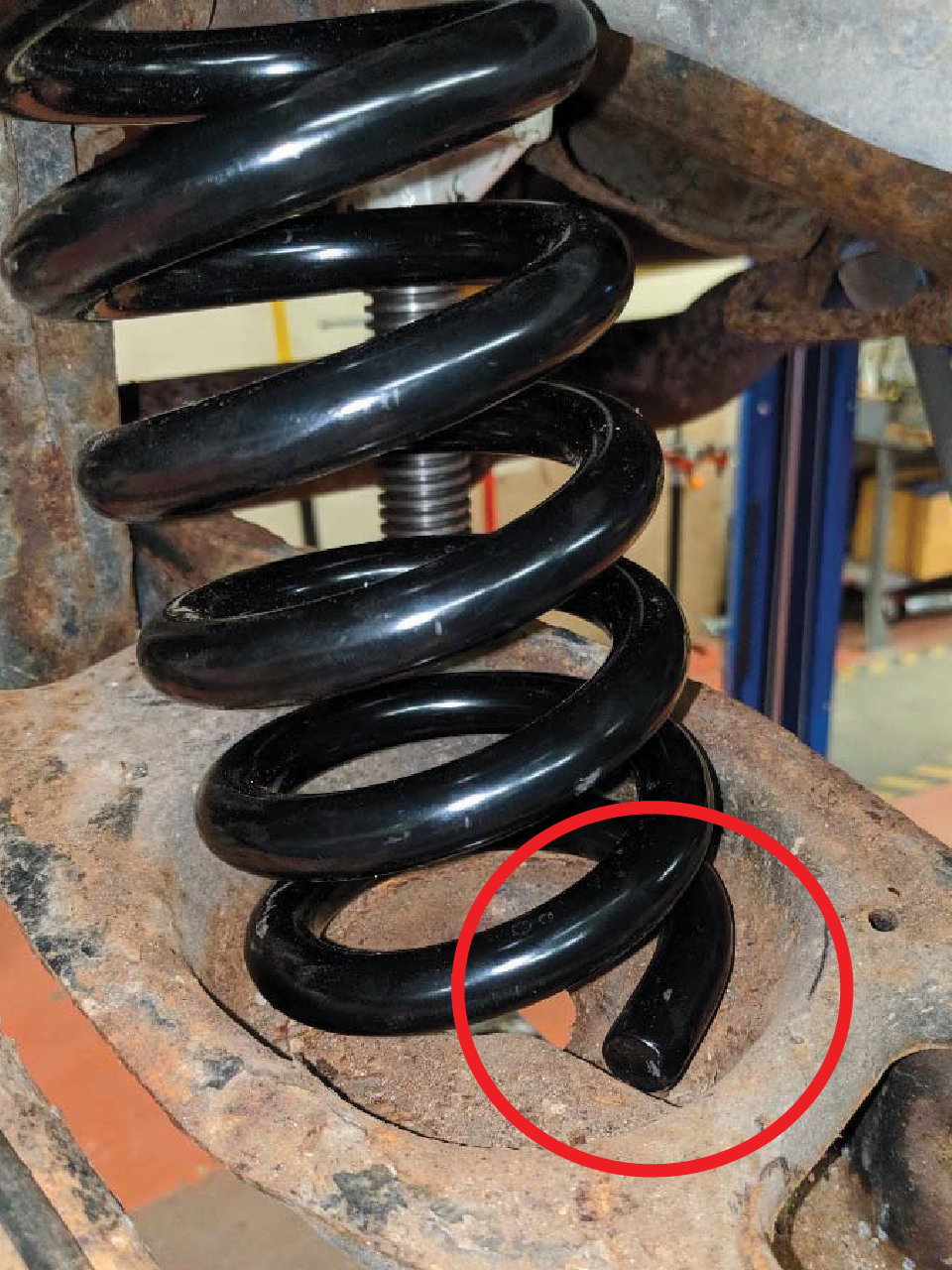
Note: Ensure that the end of the pig tail butts up against the step in the lower spring seat (see photo below).
Caution: Take care that vehicle weight does not shift off frame supporting points when lifting the axle.
Note: Repeat all steps for opposite side of vehicle. Then proceed to step 8.