For Vehicles:
- 2018-2013 Ram 1500
- Monroe part numbers required for a complete four-corner repair: 90028C1, 90028C2 and 90028C3 (each part number sold separately).
- Read this instruction sheet and any instructions printed on the parts package carefully prior to removing the components from the vehicle.
- Part number on shock or spring may differ from part number on carton. The contents are correct for the vehicle.
- For questions or concerns, contact the Gurus On Call at 1-800-325-8886.
WARNING!
- If the shocks supplied are nitrogen gas pressurized, do not heat or open.
- Always wear safety glasses for eye protection.
- Use safety stands whenever a procedure requires you to be under a vehicle.
- Before servicing any electrical component ensure the key is out of the ignition, ignition is off and the negative lead is disconnected from the battery. Refer to the owner’s manual for the correct procedure.
- All pressurized air suspension components contain high pressure air up to 220 psig. Deflate the air suspension before servicing.
- Two front strut assemblies
- Two rear coil springs
- Two rear shock absorbers
- Two rear spring isolators
- Two rear jounce bumpers
- Instruction Sheet
This kit replaces the front electronic air struts, rear air springs, rear shock absorbers, and rear jounce bumpers on the vehicles listed above. Replacing them with front passive strut assemblies, rear coil springs, conventional shock absorbers, and a modified jounce bumper.
Note: Upon the completion of the conversion, when starting the vehicle the service suspension messages will briefly display on the instrument cluster and will automatically clear after a few seconds. This is a minor nuisance which does not affect the operation of the vehicle after the conversion is completed.
- Follow the deflation procedure in the service manual. Once the suspension is deflated raise vehicle by proper lift points making sure the vehicle is properly supported.
- Remove the front wheels.
- Remove the upper anti-sway bar end link nut, cushion, and retainer.
- Remove the outer tie rod end.
- Disconnect upper ride height sensor arm from the upper control arm. Disconnect the ride height sensor connector. Remove ride height sensor and bracket assembly from the frame. Protect connector with electrical tape or poly bag and use a zip tie to secure to the frame.
- Separate the upper ball joint from the spindle assembly. Caution: Do not over extend the brake hose and wheel speed sensor wiring. If needed, remove brake caliper adapter along with brake caliper. Hang caliper from suspension or frame. Also, disconnect wheel speed sensor wiring from the knuckle if needed.
- Support the lower control arm and remove the lower strut mounting bolt.
- Disconnect the air fitting from the top of the strut assembly using an open ended wrench. Protect air line with electrical tape or poly bag and use a zip tie to secure to the frame.
- Remove the three upper strut assembly mounting nuts.
- Remove the strut assembly. If necessary remove the lower control arm support to aid in removing the strut assembly taking care not to overextend the half shaft.
- Install the new strut assembly. If necessary remove the lower control arm support while taking care not to overextend the half shaft.
- Loosely install the three upper strut assembly mounting nuts.
- Loosely install the lower strut assembly mounting bolt.
- Reinstall the upper ball joint to the spindle assembly and torque to 40 lb-ft (54 Nm) then an additional 200 degrees.
- Reinstall the outer tie rod end and torque to 22 lb-ft (30 Nm) then an additional 90 degrees.
- Loosely install the upper anti-sway bar end link, retainer, cushion and nut.
- Reinstall the front wheel and hand tighten the lug nuts. Safely lower the vehicle to the ground and torque the wheel to 140 lb-ft (190 Nm) for flanged lug nuts or 130 lb-ft (176 Nm) for cone lug nuts.
- Torque the three upper strut assembly mounting nuts to 45 lb-ft (61 Nm).
- Torque the lower strut mounting bolt to 155 lb-ft (210 Nm).
- Torque the upper anti-sway bar end link to 16 lb-ft (22 Nm).
- Repeat steps 1-20 for the other side of the vehicle.
- Raise vehicle by frame at proper lift points and make sure the vehicle is properly supported.
- Support the rear axle.
- Remove the rear wheels.
- Remove the rear wheel housing splash shield.
- Remove the air springs by disengaging the three clips, one at a time, on the top of the air spring. Support the bottom of the air spring and remove using caution as the air line is still connected. Disconnect the air fitting from the top of the air spring using an open ended wrench. Protect air line with electrical tape or poly bag and use a zip tie to secure to the frame.
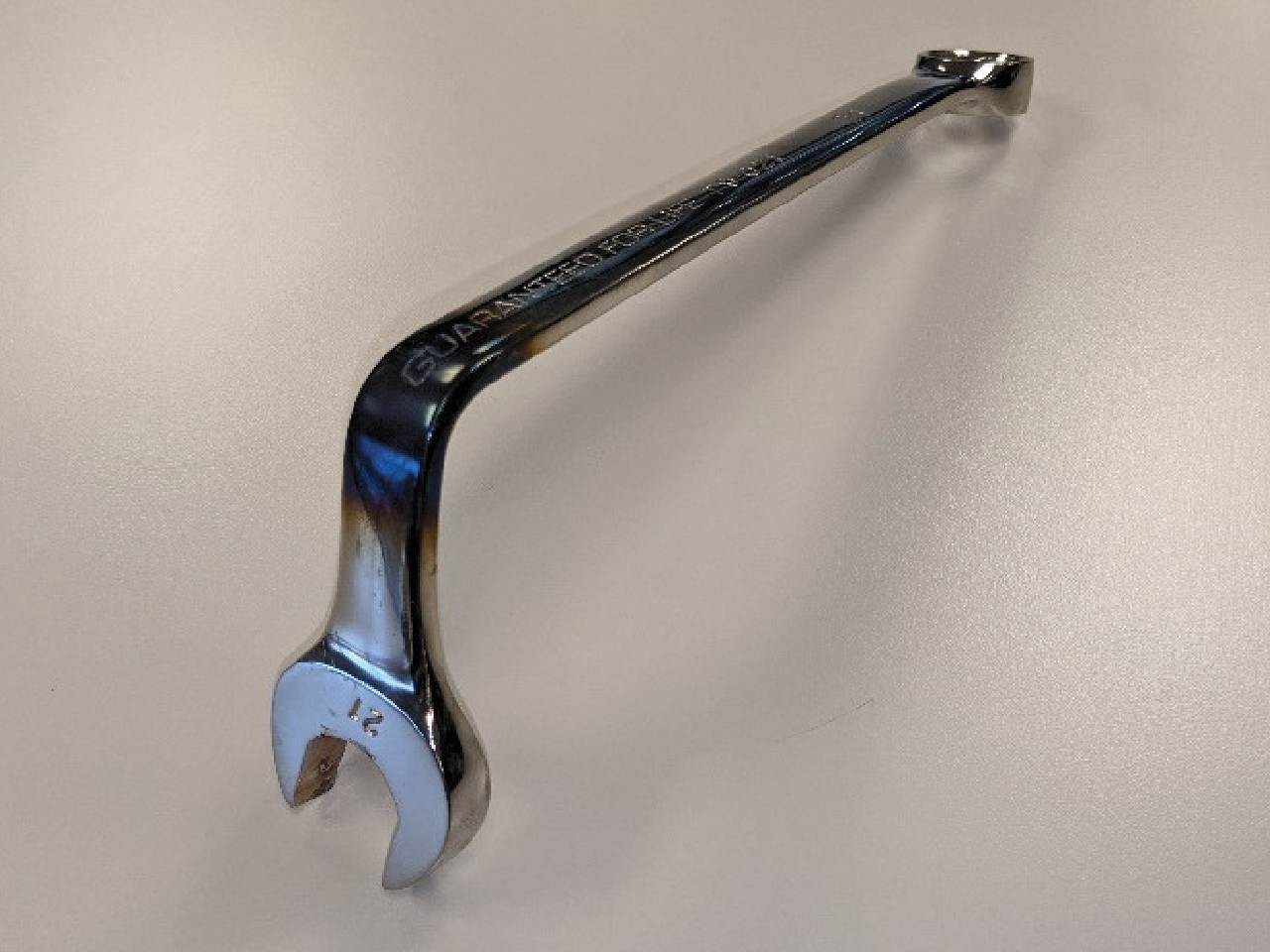
- Remove the rear shock absorbers. Note: A modified 21mm wrench may be needed to access the upper shock absorber nut for the mounting bolt. See photo below.
- Disconnect rear ride height sensor arms. Disconnect the ride height sensor connectors. Remove ride height sensors and bracket assemblies from the frame. Protect connectors with electrical tape or poly bag and use a zip tie to secure to the frame.
- Disconnect the lower OR upper end of each of the rear anti-sway bar end link. Save hardware for reuse.
- Remove the bolt holding the brake hose and wheel speed sensor cables to the frame on both sides along with the push pin body fastener on the passenger side. Save hardware for reuse.
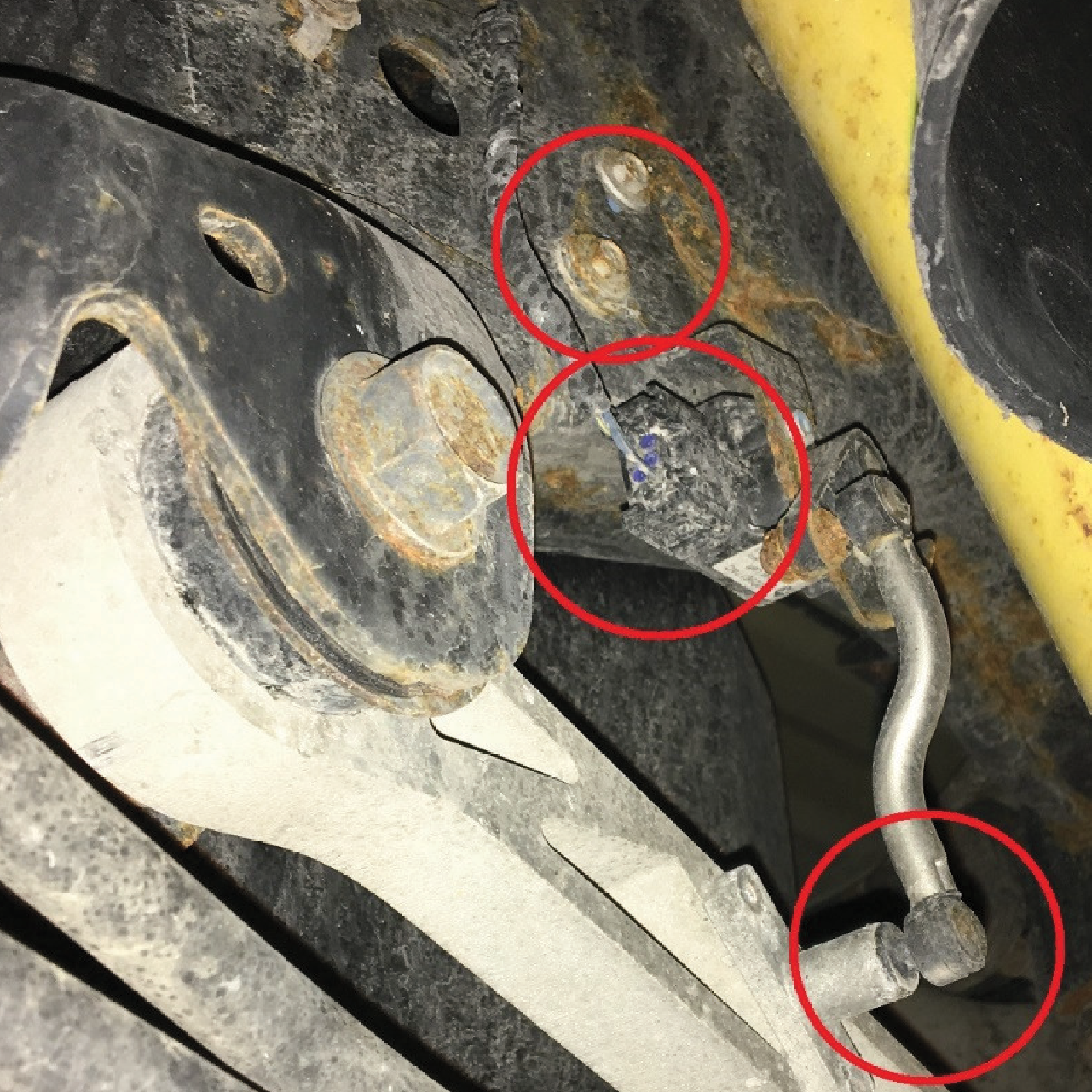
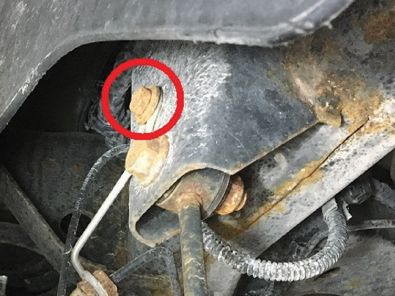
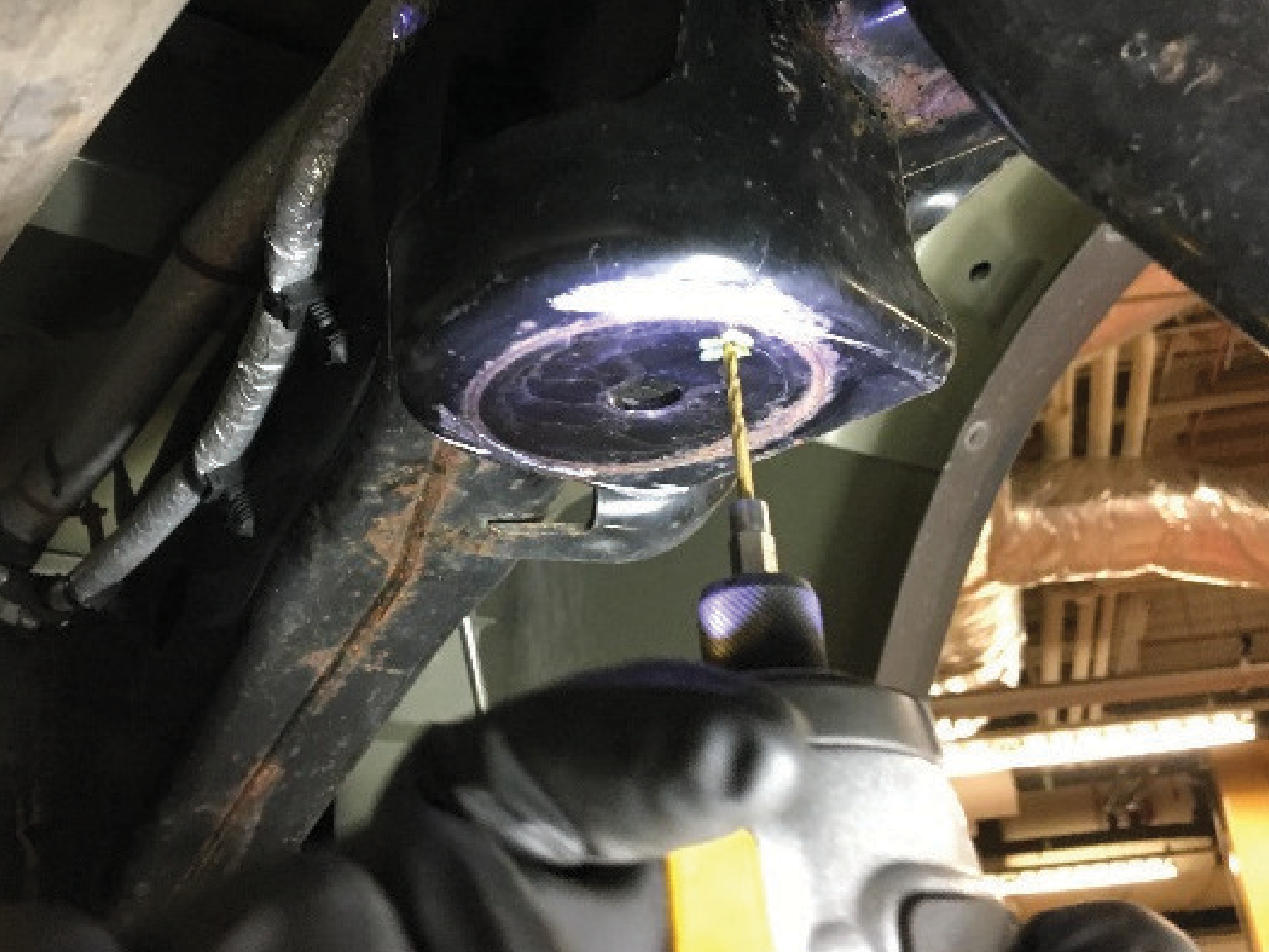
- Remove the jounce bumper extensions by cutting the welds at the bracket as shown in the photo below. Use caution to not cut into the bracket.
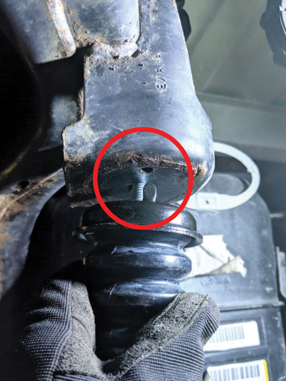
- Make a mark on the brackets 1” (25.4mm) from the centerline of the hole (any direction) and drill a 5/16” (8mm) hole. This hole is needed for the tab on the new jounce bumper.
- Test fit the bumper to ensure the hole placement and diameter is correct. Paint the bracket to prevent any corrosion.
- Once the paint is dry install the new jounce bumper and orient so the tab fits into the drilled hole on the bracket. Use the provided washer and nut and torque to 24 lb-ft (32 Nm).
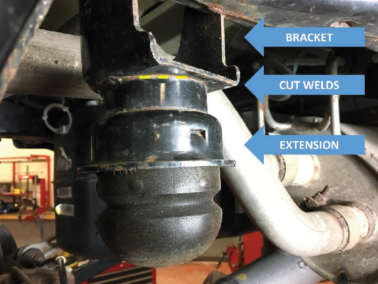
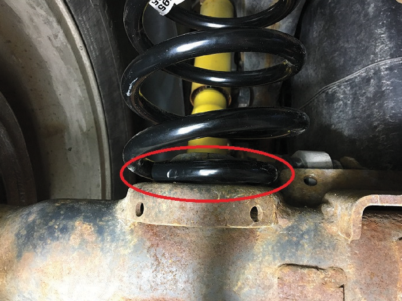
- Install coil springs and rubber spring isolators onto the axle with the larger diameter coils facing up. The rubber spring isolators need to be placed at the top end of the spring. Rotate the spring so the lower pigtail is parallel with the axle. Carefully raise the rear axle just enough to ensure the upper coils remain properly seated in the upper spring seats.
- Install new shock absorbers into the upper mounting brackets using the original hardware (inspect and replace if necessary). Hand tighten only.
- Caution: Take care that vehicle weight does not shift off of frame supporting points when lifting the axle. Continue to raise the axle until the lower shock mounts align with the lower mounting brackets. Reinstall original mounting hardware (inspect and replace if necessary). Hand tighten only.
- Reconnect the rear anti-sway bar end link reusing the original hardware. Hand tighten only.
- Reconnect the brake hose and wheel speed sensor cable brackets to the frame. Reusing the original mounting hardware torque to 15 lb-ft (20 Nm)
- Reinstall the rear wheels and hand tighten the lug nuts. Safely lower the vehicle to the ground and torque the lug nuts to 140 lb-ft (190 Nm) for flanged lug nuts or 130 lb-ft (176 Nm) for cone lug nuts.
- Torque the upper and lower shock mounting hardware to 100 lb-ft (135 Nm). Note: Modified 21mm wrench will need to be used to hold the upper nut for the mounting bolt.
- If the upper anti sway bar end link was disconnected, torque end link nut to 79 lb-ft (107 Nm). If the lower anti sway bar end link was disconnected, torque end link nut to 55.5 lb-ft (75 Nm).
- Reinstall the rear wheel housing splash shield.
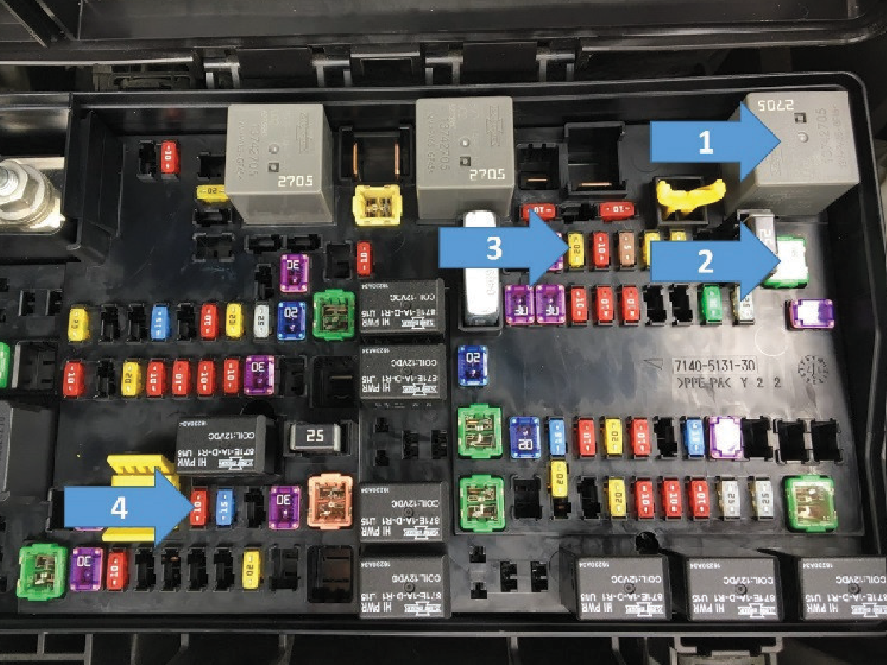
- Locate the fuse box in the left side of the engine compartment. Remove the K03 AIR SUSP relay (1), F05 AIR SUSPENSION COMP 40A fuse (2), F50 AIR SUSPENSION MOD 20A fuse (3), and F87 AIR SUSP/TT/SCCM 10A fuse (4).
- Reconnect the negative lead of the battery.
Note: When starting the vehicle, the service suspension messages will briefly display on the instrument cluster and will automatically clear after a few seconds. This is a minor nuisance which does not affect the operation of the vehicle after the conversion is completed.