For Vehicles:
- 2014-2007 Cadillac Escalade with Z55 suspension, including ESV & EXT
- 2014-2007 Chevrolet Avalanche with Autoride Z55 suspension package
- 2014-2007 Chevrolet 1500 Suburban with Autoride Z55 suspension package
- 2014-2007 Chevrolet Tahoe with Autoride Z55 suspension package
- 2014-2007 GMC Yukon 1500 with Autoride Z55 suspension package
- 2014-2007 GMC Yukon XL 1500 with Autoride Z55 suspension package
- Read this instruction sheet and any instructions printed on the parts package carefully prior to removing the components from the vehicle.
- Part number on shock or spring may differ from part number on carton. The contents are correct for the vehicle.
- For questions or concerns, contact the Monroe Technical Resource Center at 734-384-7809.
WARNING!
- If the shocks supplied are nitrogen gas pressurized, do not heat or open.
- Always wear safety glasses for eye protection.
- Use safety stands whenever a procedure requires you to be under a vehicle.
- Before servicing any electrical component ensure the key is out of the ignition, ignition is off and the negative lead is disconnected from the battery. Refer to the owner’s manual for the correct procedure.
This kit replaces the front electronic and rear electronic air shock absorbers on the vehicles listed above, replacing them with front passive strut assemblies and rear standard air shocks. The resistors in this kit are designed to replace the non-operational electronic circuit within the shocks and struts. This kit will maintain the rear air leveling portion as long as the air pump system is functional. If the air leveling pump is NOT functional Monroe recommends using conversion kit 90027C in place of 90026C.
The installation of the provided resistor(s) will maintain the electrical circuit to eliminate most “service ride control” messages, provided that the warning is caused by the electronics within the shocks and struts.
Note: This kit will not eliminate suspension warning messages caused by issues with the air leveling system. If the service suspension message appears it will have to be reset each time the vehicle is started. The message is a minor nuisance which does not affect the operation of the vehicle after the conversion is completed.
- Two front strut assemblies.
- Two rear air shock absorbers.
- Four parts packages with resistors.
- Instruction sheet.
- Raise vehicle by frame at proper lift points. Consult GM Owner Manual if necessary and make sure the vehicle is properly supported.
- Remove the front wheels.
- Support the lower control arm and remove the two lower strut mounting bolts.
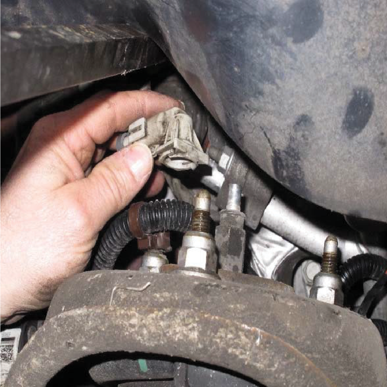
- Disconnect the electrical connector that is attached to the top of the strut rod.
- Remove the three (3) upper mounting nuts and remove the strut assembly. Note: You may need to disconnect the outer tie rod from the steering knuckle to provide more clearance for removal.
- Repeat steps 3-5 on opposite side of the vehicle.
- Install the new strut/coil spring assembly and loosely attach the three (3) upper mounting nuts. Pivot the lower control arm up into place and attach the lower mounting bolts “hand tight”.
- If the outer tie-rod end was disconnected from the steering knuckle during step 5, reinstall and torque to 44 lb-ft (60 Nm). Warning: Inspect and replace worn components/ fasteners, if necessary.
- Repeat steps 7-8 on opposite side of the vehicle.
- Reinstall the front wheels and lower the vehicle so its full weight is on the suspension and tighten the lug nuts to 140 lb- ft (190 Nm). Then tighten the upper mounting nuts to 37 lb-ft (50.2 Nm).
- Next tighten the two strut assembly lower mounting bolts to 37 lb-ft (50.2 Nm).
- To eliminate the electronic suspension, the electrical connectors will now need to have a resistor installed (provided). Refer to the instructions within the resistor parts package for this installation.
- Raise vehicle by frame at proper lift points. Consult GM Owner Manual if necessary and make sure the vehicle is properly supported.
- Support the axle prior to removal of any bolts.
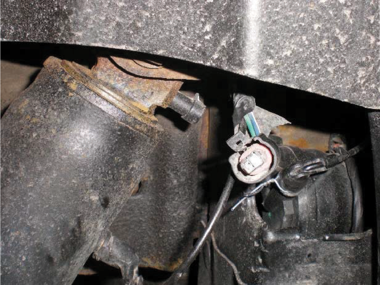
- Disconnect the air line from the shock by separating the clip and pull straight out from the fitting. Prevent contaminants from entering air line fitting.
- Disconnect the electrical connector for the electronic ride control from upper shock mount.
- Remove the upper and lower mounting bolts, save for reuse. Remove the shock absorbers.
- Install new air shocks using hardware saved from previous step. Tighten to 70 lb-ft (95 Nm).
- Reinstall the air line to the shock. There may be a protective cap over the fitting, so remove first. The original air fitting will attach by pushing directly on to fitting. The clip must be within the split area of the fitting to ensure a secure connection.
- Once both shocks are installed, air will need to be added to the shocks prior to completely lowering the vehicle. The leveling valve at the control arm can be disconnected to move manually. Before turning on the ignition and moving the valve arm upward the pump should activate. Only a small amount of air needs to inflate the air sleeve to prevent folding inside of the dirt shield.
- To eliminate the electronic suspension, the electrical connectors will now need to have a resistor installed (provided). Refer to the instructions within the resistor parts package for this installation.