For vehicles originally equipped with air leveling systems:
- 2013-2007 Ford Expedition 2WD, 4WD
- 2013-2007 Lincoln Navigator 2WD, 4WD
- Monroe part numbers required for a complete repair: 90023C1 and 90023C2 (each part number sold separately).
- Read this instruction sheet and any instructions printed on the parts package carefully prior to removing the components from the vehicle.
- Part number on shock or spring may differ from part number on carton. The contents are correct for the vehicle.
- For questions or concerns, contact the Gurus On-Call at 1-800-325-8886.
WARNING!
- Do not attempt to service or remove the air spring from suspension if still containing air. Release the air from the spring before servicing.
- If the shocks supplied are nitrogen gas pressurized, do not heat or open.
- Always wear safety glasses for eye protection.
- Use safety stands whenever a procedure requires you to be under a vehicle.
- Before servicing any electrical component ensure the key is out of the ignition, ignition is off and the negative lead is disconnected from the battery. Refer to the owner’s manual for the correct procedure.
This kit replaces the rear air springs on vehicles listed above, replacing them with conventional coil springs. This provides a complete and thorough conversion by also eliminating the air compressor control system.
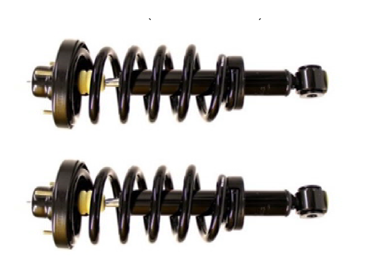
- Two rear strut assemblies
- Instruction sheet (FORM01209)
The ride height noted is after installation of the coil spring conversion. This is the same as a vehicle originally equipped with a conventional coil spring suspension. Note: The static ride height with a coil spring suspension is typically ½ inch higher than the static ride height of a vehicle with air suspension.
Height is approximate, as measured from centerline of wheel to the bottom of the fender well opening lip.
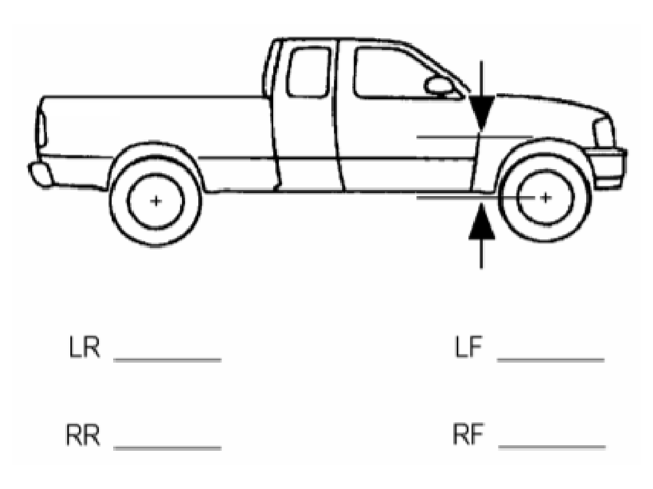
Typical Ride Heights After Conversion:
FRONT – 19 ¾” to 20 ½”
REAR – 20 ¼” to 21”
If needed, you can refer to the OE service manual for servicing the air spring air solenoid valves and for removal of the particular shock absorbers. This Instruction Sheet is a guideline and reference tool for the installation.
Some of the installation steps may require the use of special tools designed for specific procedures.
Inspect all parts as removed from the cartons for correct quantity and damage. Obtain replacements if necessary.
Additional removal procedures are packaged with each damper assembly (within individual cartons).
- The rear suspension is a complete assembly, with an air spring on the strut. With this conversion kit, the entire assembly will be removed and replaced. No parts from the original strut will be used. The air compressor system will be disabled.
- The air suspension control system should be turned to OFF prior to hoisting or jacking vehicle. All doors must be closed and the ignition turned ON. Select the “SETUP” control function on the message center. Select the “AIR SUSPENSION” function to display current status, then press the “RESET” button to turn the air suspension to “OFF”.
- The vehicle can now be raised at proper lift points and properly supported. It is not necessary to remove the wheel and tire assembly.
- With the vehicle lifted to gain access to the strut assembly, you will need to exhaust air from the system. You can either disconnect the solenoid from the strut assembly or disconnect the air line and electrical connector from the solenoid.
- To remove the solenoid and release the air from the air springs, remove clip from solenoid and rotate the solenoid valve counter-clockwise to the first stop. This will allow the air in the spring and system to slowly escape. The solenoid may then be removed after all air has been exhausted. The solenoid valve will remain on the vehicle and should be bagged and ziptied in a safe location. Note: Provided the solenoid valves and air springs are still functional, these should be retained if the air system is ever to be reinstalled.
- To remove the air strut assembly, remove the lower strut mount bolt at the lower control arm. Save bolt for reuse. Disconnect the lower end of the ride height sensor link from the lower control arm. Next, remove the lower inner control arm to frame bolt and nut. Pry down on the lower control arm and pivot out of the way. Support the air strut by the lower mount.
- Next remove the three (3) upper mounting nuts and the air strut assembly from the vehicle.
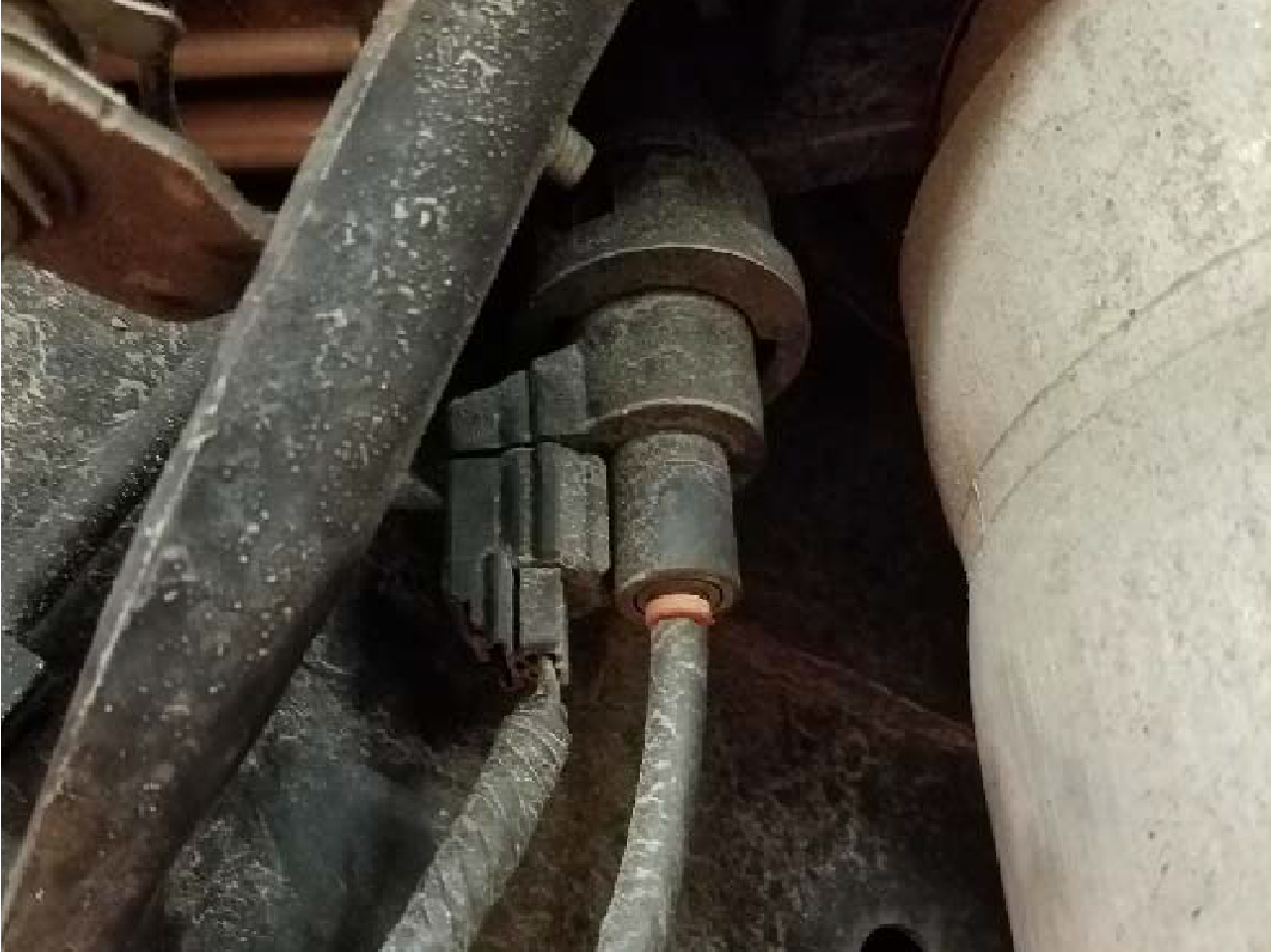
The other option is to disconnect the air line and the electrical connector from the solenoid on the strut assembly. To remove the air line push in on the plastic ring at the fitting surrounding the air line, while pulling out on the air line. You can also cut the air line near the fitting if it cannot be removed due to corrosion. Caution: Air may escape rapidly. Next disconnect the electrical connector by pressing in on the tab while pulling down on the connector.
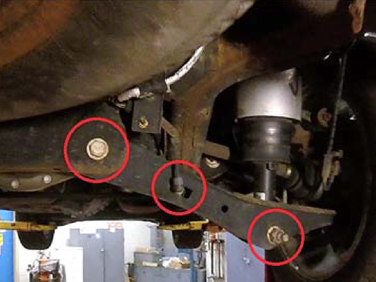
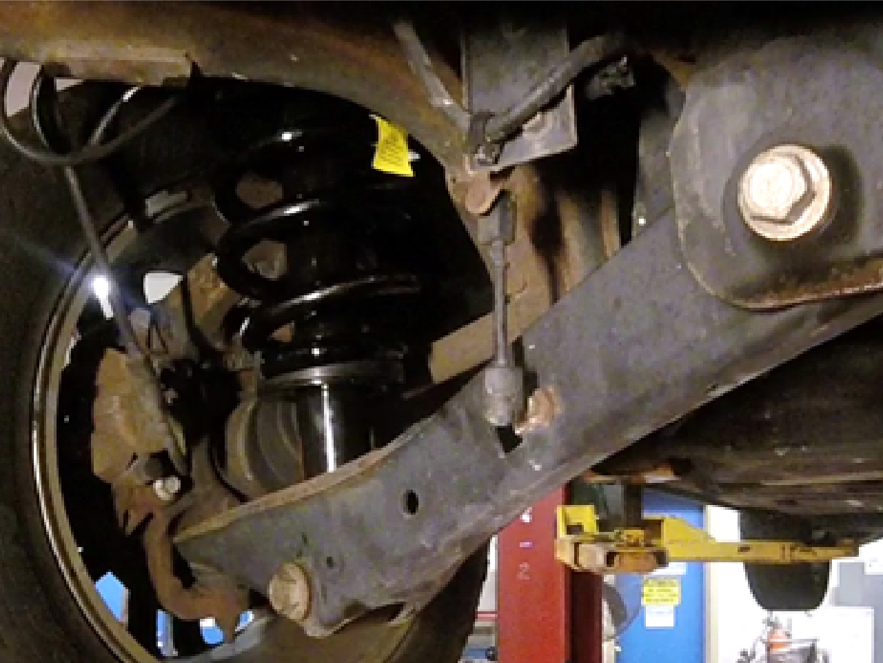
- Install the new strut/coil spring assembly. Installation essentially is reverse to the removal of the air strut assembly. The strut/spring coil assembly is identical to that sold as a replacement for vehicles originally equipped with non leveling suspension.
- Loosely attach the three (3) upper mounting nuts. Pivot the lower control arm back into place and loosely attach the lower mounting bolt and the lower control arm to frame bolt and nut. Reattach the right height sensor link to the lower control arm.
- Lower the vehicle so its full weight is on the suspension. Then tighten the upper mounting nuts to 30 lb-ft (40.6 Nm).
- Tighten the strut assembly lower mounting nut to 350 lb-ft (475 Nm), and the lower control arm to frame bolt to 266 lb-ft (225 Nm).
This part of the procedure relates to disabling the warning systems for the Air Ride Suspension. Failure to follow this part of the instructions will lead to visual and/or audible warnings. If the instrument panel module is not re-flashed as outlined below, the reset button for the information center will need to be pressed after each startup. The warnings will not harm the operation of the vehicle after the coil spring conversion, but may be an annoyance.
NOTE: The following steps are intended for use by professional technicians who possess an understanding of proper programming/re-flashing techniques and procedures. Vehicle owners can contact a local service repair facility to have the following procedure completed at a nominal fee.
Warning: Failure to follow proper reprogramming procedures may result in the loss of functionality of vehicle control systems.
Required items:
- Laptop with corded AC power supply.
- Automotive battery maintainer/charger.
- J2534 reprogramming tool.
- Reprograming software (Ford Module Programming, Forscan, etc.).
- Stable internet connection (wired preferred)
- Connect a battery maintainer to the vehicle battery to ensure proper voltage during programming. Warning: Follow instructions included with battery maintainer/charger for safe operation.
- Power up the laptop with the AC power adapter and a stabile internet connection. Connect the J2534 reprogramming tool to the laptop and the vehicle OBD-II port. Launch the reprogramming application and follow the onscreen instructions for communicating to the vehicle.
- Access the IC (Instrument Cluster) module and backup existing parameters. Once backed up, only configure the first line (720-01-01) to display 91 05 7D FF 3B. Any additional programming lines should remain unchanged (configured as built). Note: To configure only one line of code in some reprogramming software the module may have to be accessed as if it is a new module installation (Programmable Module Installation).
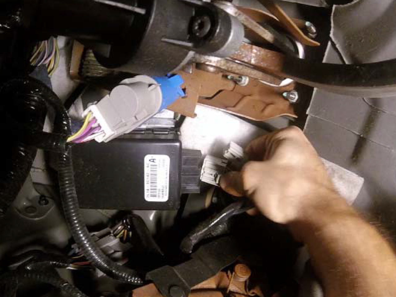
Note: Once programming is completed, the air suspension option and warnings will no longer be visible in the instrument cluster. However, the air suspension module will continue to function until physically disconnected. - Ensure the key is out of the ignition, ignition is off and the negative lead is disconnected from the battery. Then locate the air suspension module under the dash to the left of the brake pedal assembly. Unplug both connectors. The air suspension is now completely disabled.
- Reconnect the negative battery lead. The conversion is now complete.