For Vehicles Originally Equipped with Air Suspension:
- 2007 and later Cadillac Escalade w/ Z55 suspension package
- 2007 and later Cadillac Escalade EXT
- 2007 and later Cadillac Escalade ESV
- 2007 and later Chevrolet Tahoe, w/ Autoride Z55 suspension package
- 2007 and later Chevrolet 1500 Suburban w/ Autoride Z55 suspension package
- 2007 and later GMC Denali (Yukon)
- 2007 and later GMC Yukon w/ Autoride Z55 suspension package
- Monroe part numbers required for a complete four-corner repair: 90013C1 & 90013C2 (each part number sold separately)
- Read this instruction sheet and any instructions printed on the parts package carefully prior to removing the components from the vehicle.
- Do not grip the polished piston rod of a shock with any tool. Nicks or scratches will reduce the shock absorber's service life.
- Part number on shock or spring may differ from part number on carton. The contents are correct for the vehicle.
- For questions or concerns, contact the Gurus On Call at 1-800-325-8886.
WARNING!
- Before servicing these vehicles equipped with original air leveling shocks, turn off the "air suspension switch" if available.
- Do not attempt to remove the air shock from the suspension if it still contains air. Release the air from the air spring before servicing.
- If the shocks supplied are nitrogen gas pressurized, do not heat or attempt to open.
- Always wear safety glasses for eye protection.
- -Use safety stands whenever a procedure requires you to be under a vehicle.
This kit described in these instructions replaces the front electronic and rear electronic air shock absorbers. The components will replace the electronic portion of the system on the vehicle, but will still maintain the air leveling portion.
The FRONT is a passive replacement of the original spring over shock absorber. All components for the installation are provided. The parts package with the “resistor” will maintain the electrical circuit to eliminate any “service ride control” message caused by the multi stage electronic control within the shock absorber.
The REAR is a passive replacement of the original air leveling shock absorber. This replacement passive air shock will still provide air leveling, but will eliminate the electronic portion of the system, provided the air pump is still functional. All components for this installation are provided. The parts package with the “resistor” will maintain the electrical circuit to eliminate any “service ride control” message caused by the multi stage electronic control within the shock absorber.
If the air leveling pump is NOT functional, this will need to be repaired or replaced. If this is not corrected, the same “service ride control” message will occur.
This installation can be completed if the air pump is eliminated by obtaining and installing a manual fill air line kit AK29 (not provided within conversion kit), which will abort the pump leveling system. The pump system will need to disconnected, which will remove the error from the message center.
Recommend that installation of all shock absorbers be completed first, then complete all electrically conversions/installations afterward.
This kit is designed to provide a conversion of the suspension, along with disengagement of the pump system if so required. This conversion contains the necessary instructions to eliminate the electronic warning signals on some models. Some additional components may be required for certain vehicles, if denoted.
Inspect all parts as you remove them from the vehicle for any potential damage. Obtain replacements where necessary.
- Make sure that ignition switch is in the OFF position. Raise vehicle at recommended lift points and remove wheels (consult GM Owners or Service Manual if necessary) and make sure the vehicle is properly supported..
- Remove the two lower mounting bolts to the damper assembly from lower control arm and save for reuse.
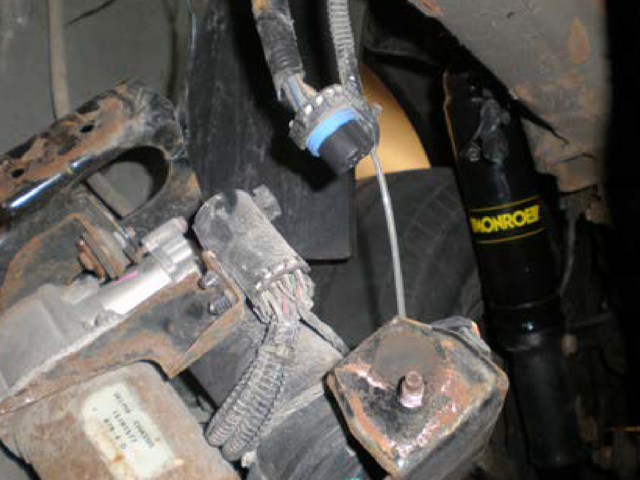
- (FIG. 2, FIG 3, FIG 4) Locate the upper mounting and electrical connector above the strut. Pull the retaining clip from the connector, then pull the connector straight up to remove (disconnect).
- Once connector is removed, the three mounting nut may be removed to allow the complete strut module to be removed from the vehicle. DO NOT remove the center nut until the complete assembly can be placed in a spring compressor to relieve spring load. All new components for upper end will be provided.
- The spring over shock absorber must be placed into aspring compressor for disassembly. Relieve spring load and remove only the center nut. Disassembly is required to retrieve some components. The new components supplied are upper mounting, upper isolator, shock absorber, new spring, new damper with lower spring seat and isolator. The original jounce bumper and dirt shield are to be reused. Careful attention to component order should be maintained for reassembly. Attention to the orientation of the upper mounting to lower mounting must be correct to reinstall. The reason new upper mounting and spring items are included is due to size differences from a vehicle with electronic components versus a conventional passive damper (12mm versus 10mm stem). Thus for proper fit, must use components provided as indicated.
- By using the original damper disassembly as a guideline, the new components should be reassembled is same order. Using the new damper, install the spring in the correct orientation, install jounce bumper on rod, dirt shield, upper isolator oriented to spring, then upper mounting plate. The mount stud heads MUST be clocked to fit the isolator, as they must rest within the relief areas of the upper isolator, which assures orientation. Once complete, install the rod nut and tighten to 30 ft-lbs (40 N-m). Relieve load from spring compressor. Review assembly for orientation and correct assembly prior to installing on vehicle.
- Install module back into vehicle. The three studs for upper mounting have an orientation which coincide with the lower, thus once the unit is installed on the upper end, the lower end should be aligned. If not, the module was not properly assembled and MUST be corrected. If correct, tighten the upper stud nuts to 30 ft-lbs (40 N-m).
- Align the lower mounting to the holes to the lower control arm. Install original bolts and tighten to 35 ft-lbs (47 N-m).
- Repeat for opposite side.
- To eliminate the electronic suspension, the electrical connectors will now need to have a resistor installed (provided). Refer to the instructions within the part package for this installation. The use of a heat gun is needed at this point for shrinking the insulation over the electrical connections. Recommended that the entire vehicle shock absorbers are installed first, then install resistor kits on all four corners for consistency.
- Again, make sure that ignition switch is in the OFF position. Raise vehicle at recommended lift points and remove wheels (consult GM Owners or Service Manual if necessary) and make sure the vehicle is properly supported.
- Support the axle prior to removal of any bolts, suggest completing one side at a time.
- Remove the air line from the shock by separating the clip and pull straight out from the fitting. Prevent dirt from entering the end of this air line.
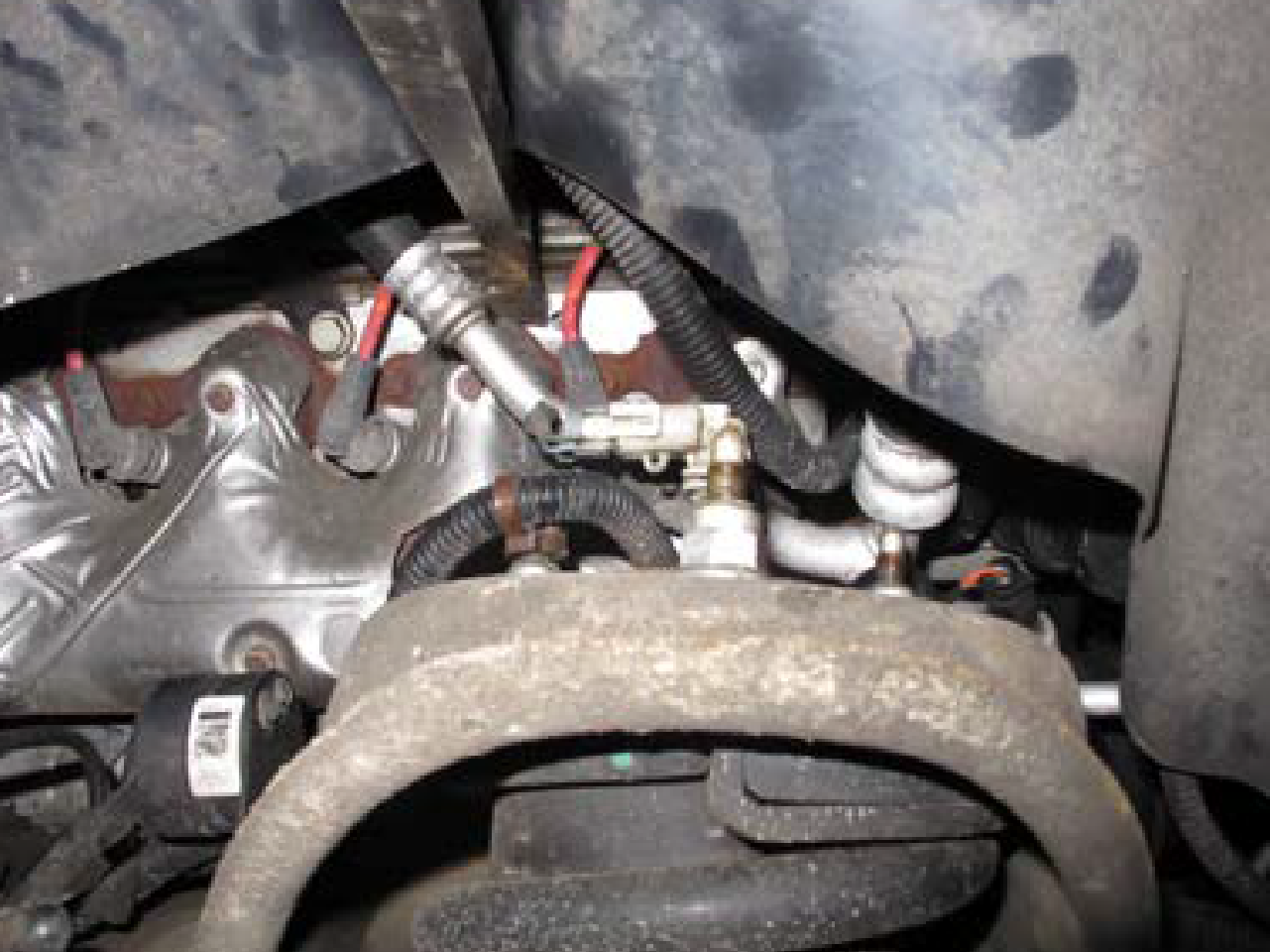
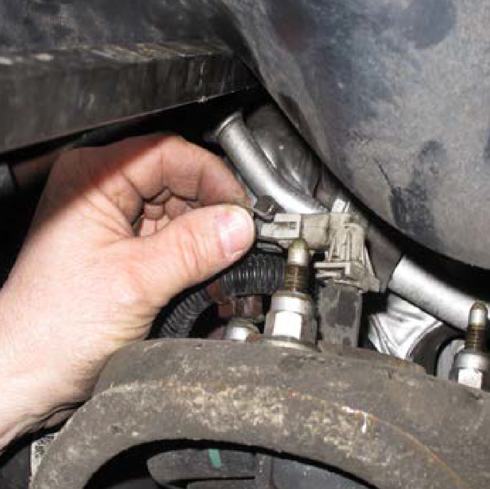
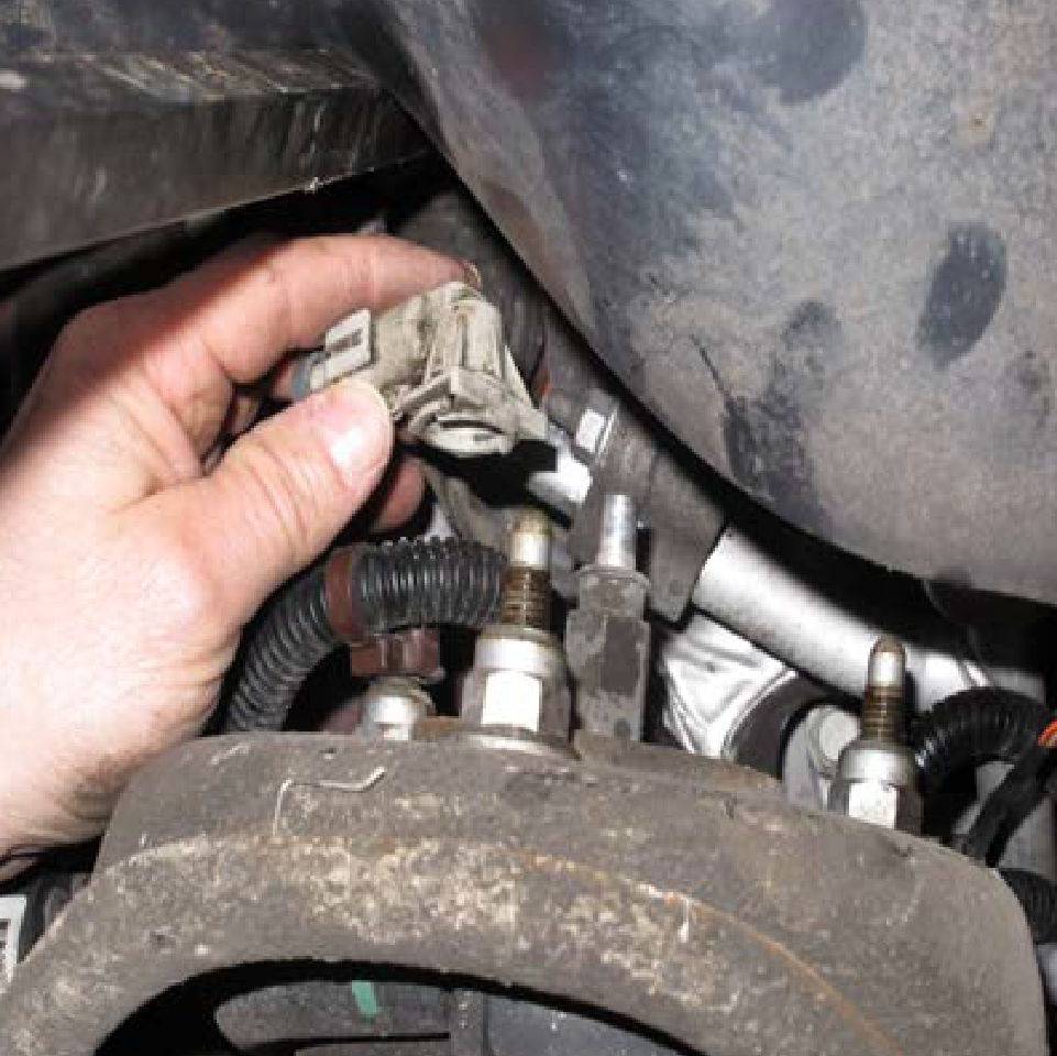
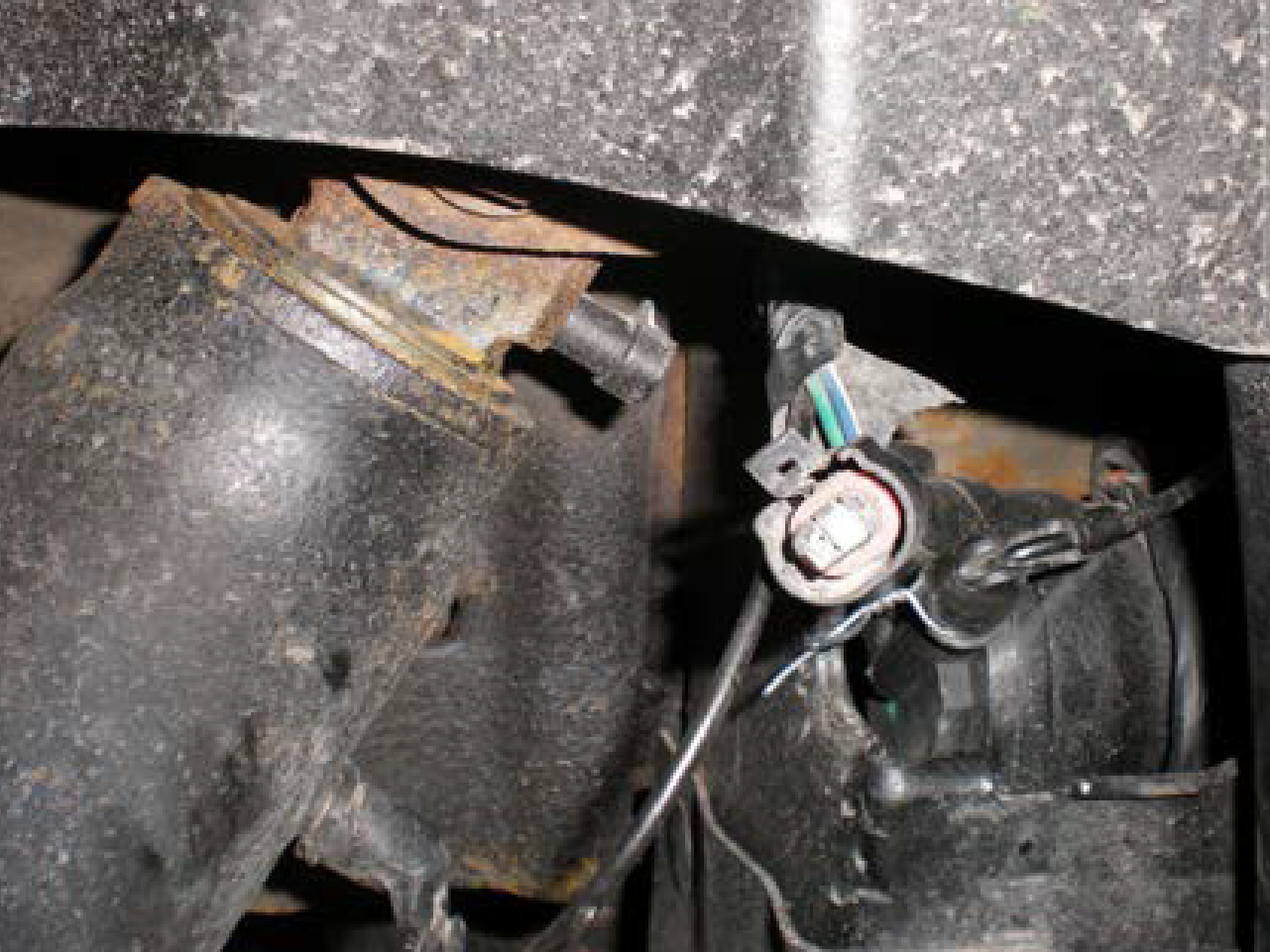
- (See image above) Disconnect the electrical connector for the electronic ride control from the rearward portion of the shock.
- Remove the upper and lower mounting bolts, save for reuse. Remove shock absorber assembly from vehicle.
- The new shock absorber assembly can now beinstalled. Tighten bolt to 42 ft-lbs (57 N-m).
- Reinstall the air line to the shock. There may be a protective cap over the fitting, so remove first. The original air fitting will attach by pushing directly on to fitting. The clip must be with the split area of the fitting as secure lock. Air will need to be added to shock prior to vehicle being set to static height, see step 9.
- Repeat for opposite side.
- Once both shocks are installed, air will need to added to shocks prior to vehicle being set to static height. The leveling valve at the control arm can be disconnected to move manually. By turning on ignition and moving the valve arm upward the pump should activate. Only a small amount of air needs to inflate the air sleeve to prevent folding inside of dirt shield.
- To eliminate the electronic suspension, the electrical connectors will now need to have a resistor installed (provided). Refer to the instructions within the part package for this installation. The use of a heat gun is needed at this point for shrinking the insulation over the electrical connections. Recommended that the entire vehicle shock absorbers first, then install resistor kits on all four corners for consistency.
As noted previously, a resistor is installed (provided) on all four corners. Refer to the instructions within the part package for this installation. This part of the procedure relates to disabling the warning systems for the Electronic Ride Control Systems. Not completing this part of the instruction will lead to visual and/or audible warning signals or messages. However, this will NOT harm the operation of the vehicle. The message or warning may be an annoyance after the conversion, but the suspension is fully operational.
This part of the procedure relates to disabling the warning systems for Air Compressor Pump Control. It is recommended that you continue to use the on board leveling system pump if possible, even if this requires the replacement of the pump itself (sold separately, not included in kit).
The remainder of this procedure to be used ONLY if conversion has been completed and no longer planning on using the on-board leveling compressor pump. Then this pump needs to be disabled. Manual air fill lines will need to be utilized. Not following this part of the instruction will lead to visual and/or audible warning signals or messages, again which will not harm the operation of the vehicle. The message or warning may cause annoyance after the conversion, but the suspension is fully operational. If needed, you can refer to the original equipment service manual for servicing the air leveling system using a scan tool. Several codes will detect air system is still functional or indicate items in question. The scan tool can also reset any error codes causing message lights or message center to be illuminated.
- If conversion has been completed to no longer use the on-board leveling compressor pump, this needs to be disabled. Remove the splash shield to gain access to the pump. Unplug the pump from the electrical system.
- It is advised NOT to remove the dedicated fuse within the fuse block for the air leveling pump, typically it is a 30 or 50 amp. The fuse does eliminate operation of the compressor pump but disengages the circuit for the leveling valves. This will trigger fault code C0660 and C0711 for compressor and leveling system errors.