For Vehicles:
- 1998-1993 Lincoln Mark VIII
- Read this instruction sheet and any instructions printed on the parts package carefully prior to removing the components from the vehicle.
- Do not grip polished piston rod with any tool. Nicks or scratches will cause decreased service life.
- Part number on shock or spring may differ from part number on carton. The contents are correct for the vehicle.
WARNING!
- If this unit is gas pressurized, do not heat or open.
- Always wear safety glasses for eye protection.
- Use safety stands whenever a procedure requires you to be under a vehicle.
This kit REPLACES both front air-suspension struts and the rear suspension system from 1993 to 1998. WARNING: PARTIAL CONVERSION OF THE VEHICLE WILL LEAD TO DANGEROUS DRIVING CONDITIONS. This kit is designed to provide a complete and thorough conversion of the suspension structure. This system will not interfere with the vehicle’s other electronic systems, and it will not drain the electronics. It is necessary that these instructions be followed to insure that no electronic warning signals result.
It is recommended that an original equipment service manual be obtained prior to replacing these particular dampers. This instruction sheet is a guideline and reference tool for the installation of the coil spring units. Due to the difficulty of this installation it is necessary to follow the steps and methods detailed to ensure quality completion.
Some of the service procedures require the use of special tools. The following tools and supplies are recommended for proper installation of this system:
- Ford Service Manual.
- Torque Wrench (200 ft-lbs).
- Heavy Duty Floor Jack Stands.
- Mallet.
- Safety Glasses/Stands.
- Assorted 1/2” Drive Ratchet and Sockets.
- Spring Compressors.
- Hydraulic Floor Jack.
- Hammer.
- Silicone Spray Lubricant.
- Assorted Combination Wrenches.
Inspect all original parts as removed from the cartons for correct quantity and damage. Obtain replacements when necessary.
99003 - Front, Right
- Strut Assembly, Right
99004 - Front, Left
- Strut Assembly, Left
99102 - Rear, Right and Left
- Shock - (Quantity: 2)
- Coil Spring - (Quantity: 2)
- Strut-Mate - (Quantity: 2)
- Spring Isolator - (Quantity: 4)
- Parts Package - (Quantity: 1)
- Upper Spring Seat - (Quantity: 2)
- Lower Spring Seat, longer bolt - (Quantity: 2)
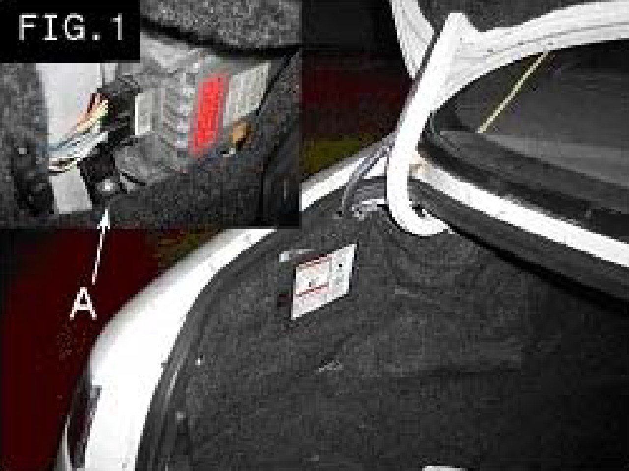
- Prior to lifting vehicle and removing wheels, turn off air suspension control switch (A), which is located on the left hand side of the trunk. Turn the ingnition switch to OFF position.
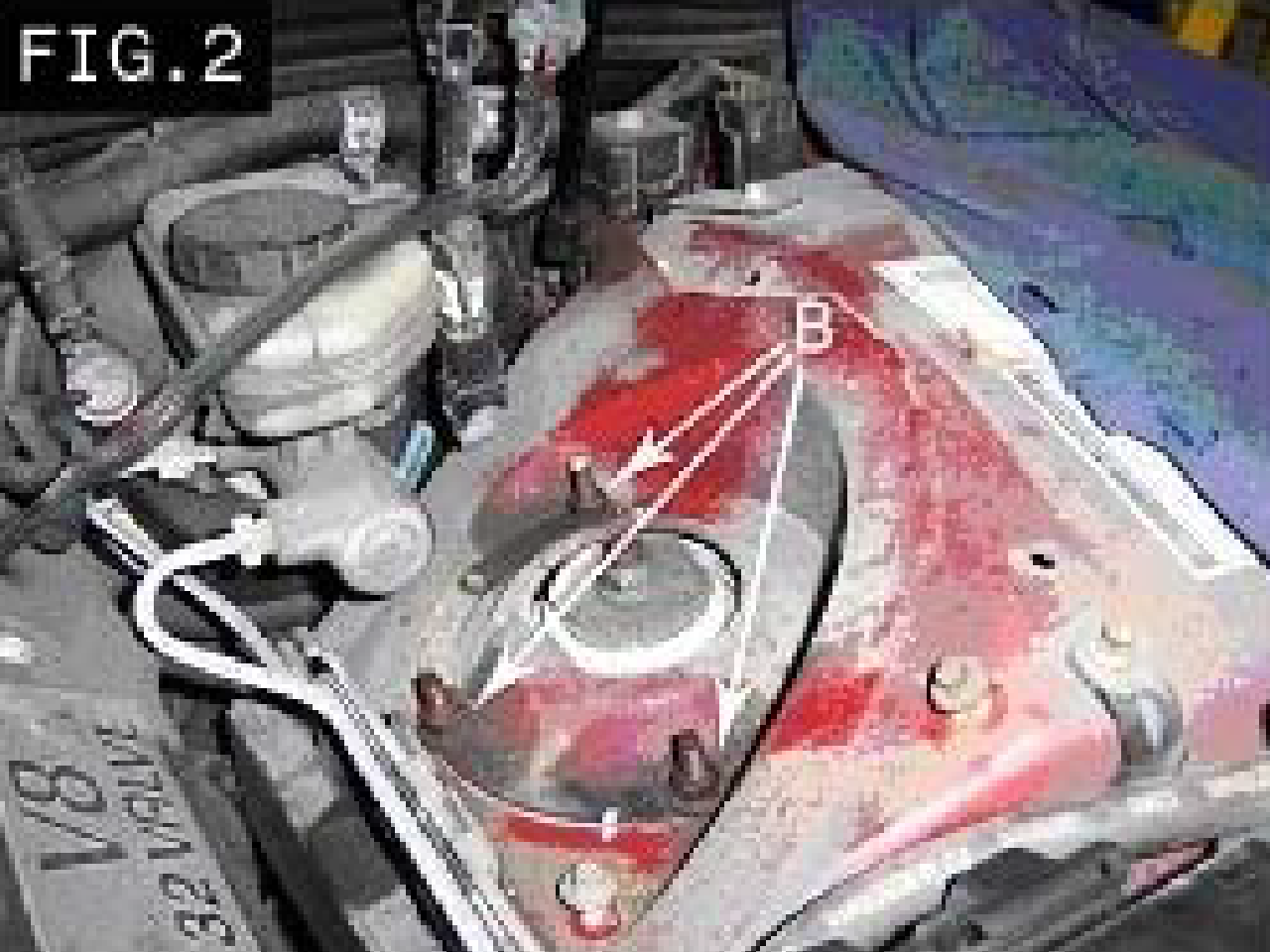
- Remove plastic cover from shock tower to expose upper Tower Nuts (B). Place aside. Loosen but do not remove the three upper Tower Nuts (B) at this time.
- Raise vehicle at proper lift points and remove wheels. (Consult Ford Owners Manual). CAUTION: Make sure the vehicle is properly supported.
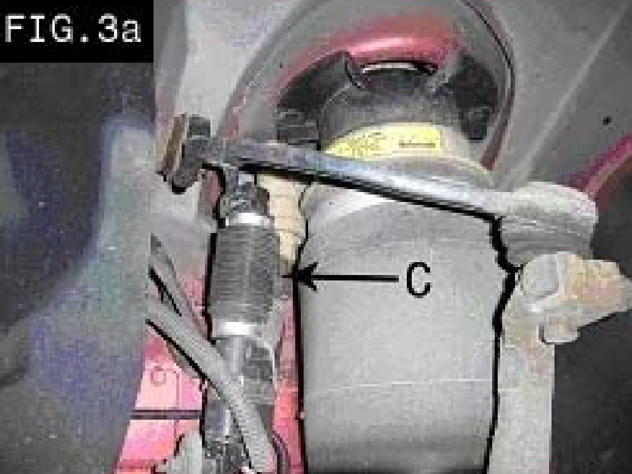
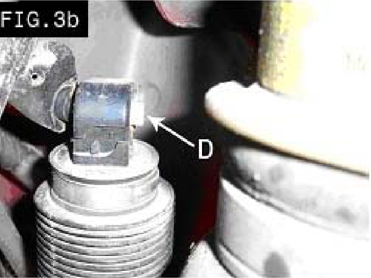
- (FIG. 3a and 3b) Remove the height sensors (C) by prying the metal clips (D) back enough to slide the end mounts off each ball strut.
- Move the ABS Sensor aside and away from any possible damage to the wire. Disconnect the stabilizer bar link and inspect for wear. If necessary, obtain replacement part.
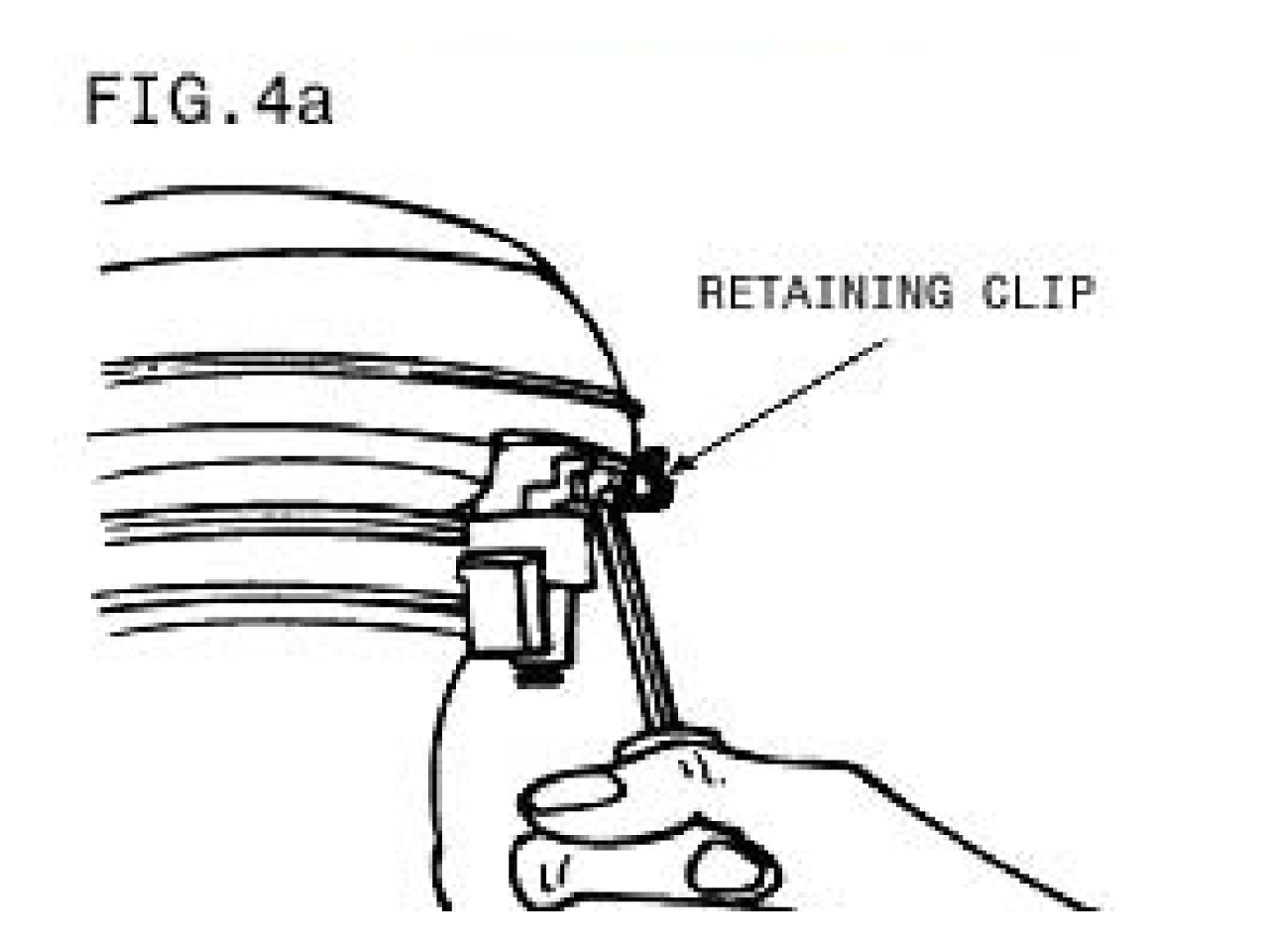
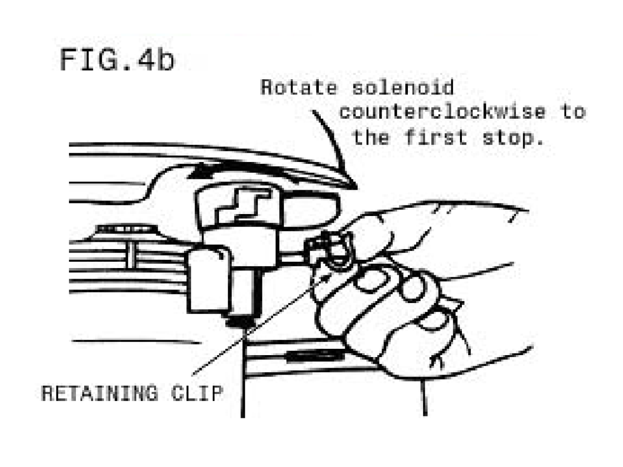
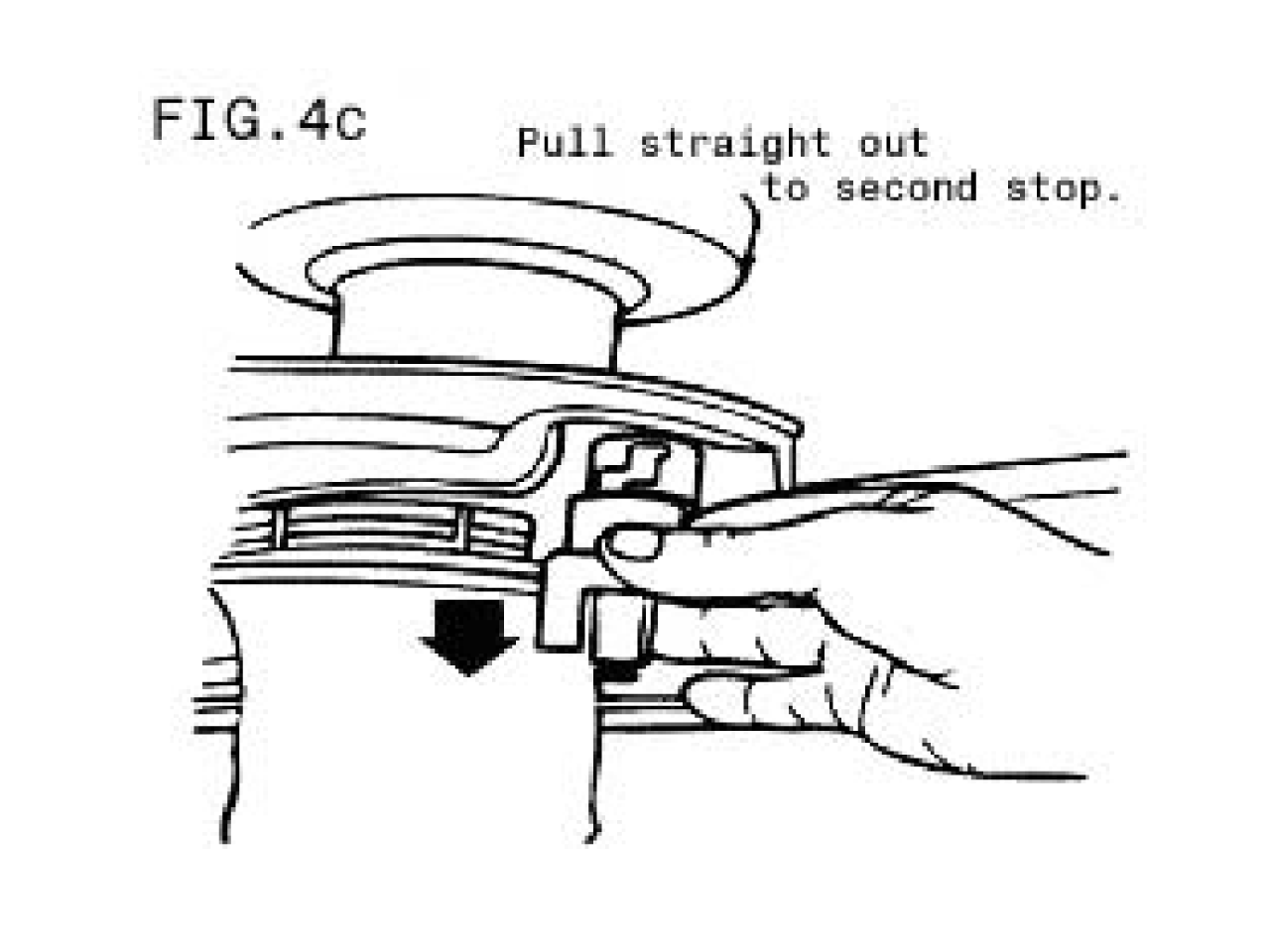
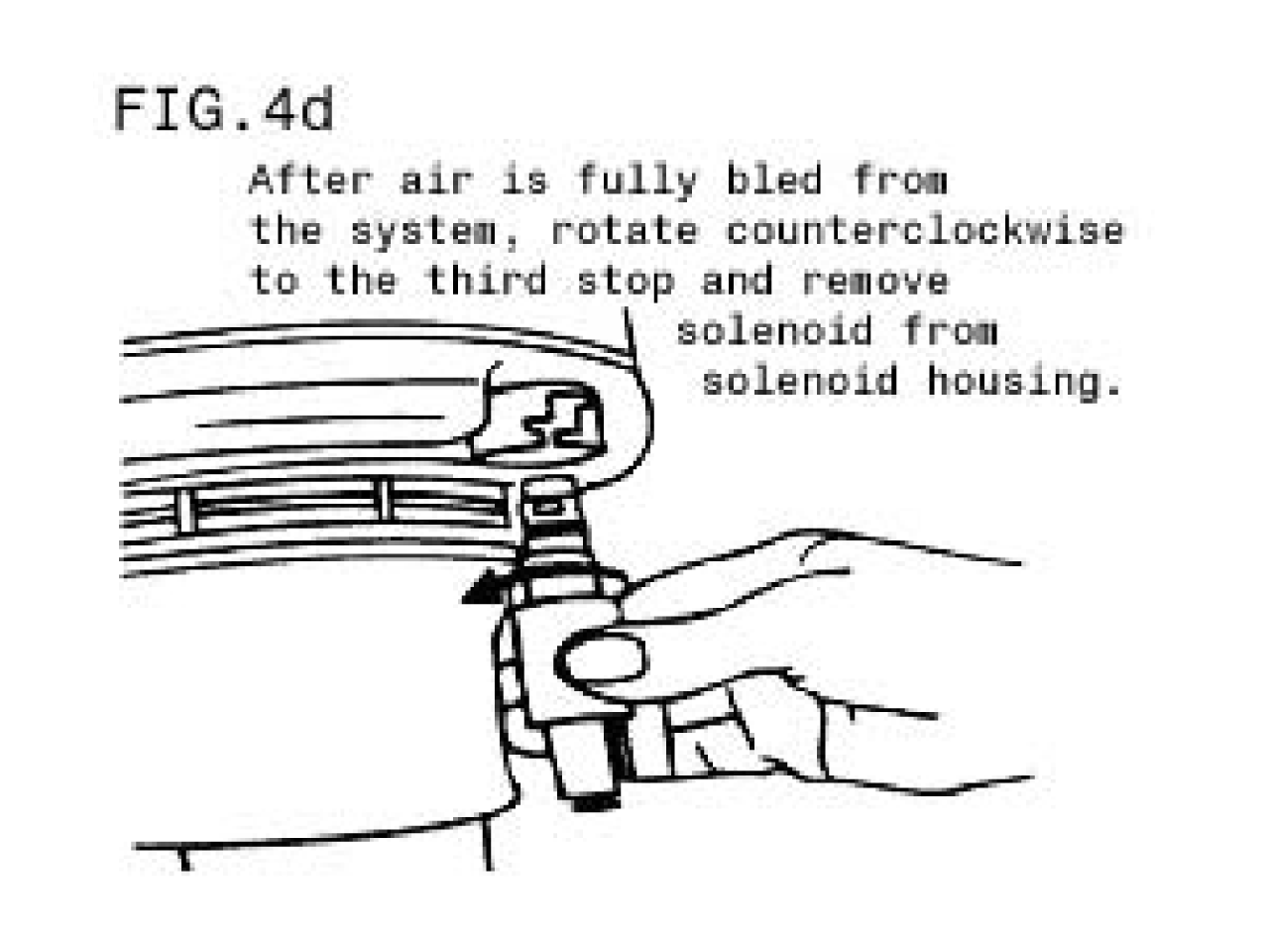
- (FIG. 4a, 4b, 4c, and 4d) CAUTION: All air must be bled from strut before removing solenoid. Remove the electrical wire and clip from solenoid valve. Remove air line from valve by pushing up on brass ring. Remove the solenoid valve from strut by rotating counterclockwise to the first step. Some air will come out. Continue to rotate the solenoid valve to the second stop, and remove the solenoid from the housing.
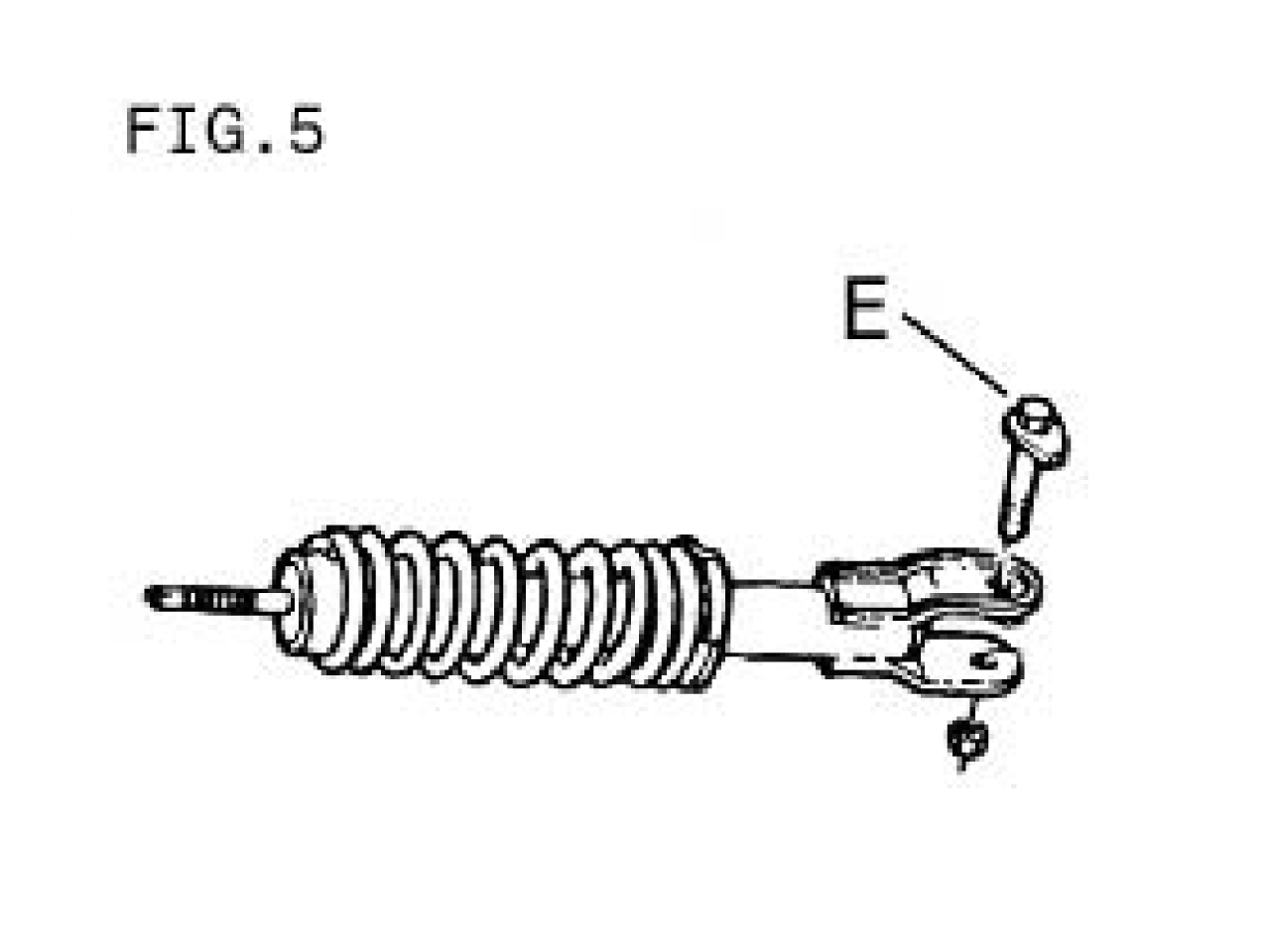
- (FIG. 2 and 5) After the solenoid valve has been disconnected, remove lower mounting bolt (E) from strut spindle mounting at lower end. Push down on lower assembly and compress strut (move upward) to separate. Once the strut is separated, remove the three tower nuts (B). Remove strut/air spring assembly from vehicle. Partially lower vehicle.
- If necessary, mark one of the upper mounting studs (B) on the new upper mount (in box 99003 or 99004) in relationship to the body for proper installation.
This part of the conversion is intended as a guideline to safeguard the electrical connectors for future reuse.
- Front:
- Verify that the height sensors and solenoids are disconnected from vehicle.
- Pull air lines and unused electrical lines into the engine compartment.
- Wrap wires and lines together in a loose bundle. Use the supplied wire tie-down to secure wires and line to existing wiring harness. CAUTION: Make sure the wires are away from all heat sources, rotating engine parts and steering components.
- Position the new strut assembly on the vehicle and install the three upper nuts (B). Torque to 16-23 ft-lbs (22-31 N-m).
- Install lower mounting bolt (E). Torque to 103-144 ft-lbs (140-195 N-m).
- Install stabilizer bar link (replace if worn) to strut and install stabilizer bar link nut. Tighten to 55-75 ft-lbs (75-101 N-m). Replace front wheels.
- Prior to lifting vehicle and removing wheels, turn off air suspension control switch (A), which is located on the left hand side of the trunk. Turn the ignition switch to the OFF position.
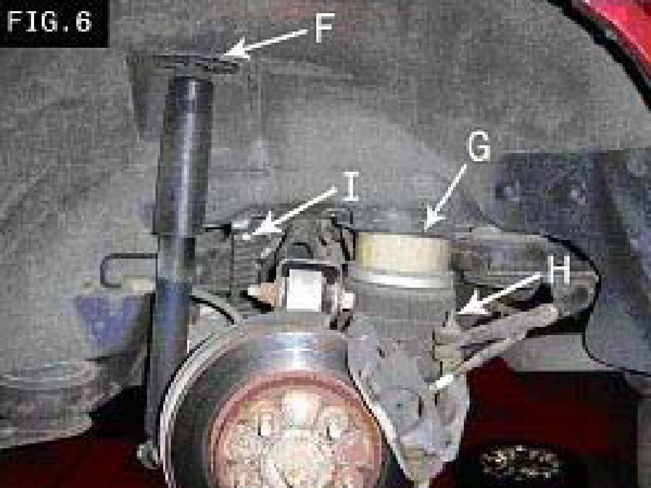
- Remove necessary interior trunk trim panels. If applicable, disconnect the electrical connection from the damping actuator in the trunk (above location “F” in FIG. 6).
- Loosen, but do not remove the two upper tower nuts at this time (in the trunk, above location “F” in Fig. 6).
- Raise the vehicle at proper lift points and remove wheels. Consult Ford Owners Manual. CAUTION: Make sure the vehicle is properly supported.
- (FIG. 4a, 4b, 4c, 4d, and 6) CAUTION: All air must be bled from air spring before removing solenoid. Remove the electrical wire and clip from solenoid valve on air spring (G). Remove air line from valve by pushing up on brass ring. Remove the solenoid valve from spring by rotating counterclockwise to the first step. Some air will come out. Continue to rotate the solenoid valve to the second stop, and the air will exhaust quickly. Rotate the solenoid valve to the third stop, and remove the solenoid from the housing.
- Remove the stabilizer bar link (H) from the stabilizer bar.
- (FIG. 3b and 6) Remove the height sensors (I) by prying the metal clips (D) back enough to slide the end mounts off each ball stud.
- Remove the rear shocks.
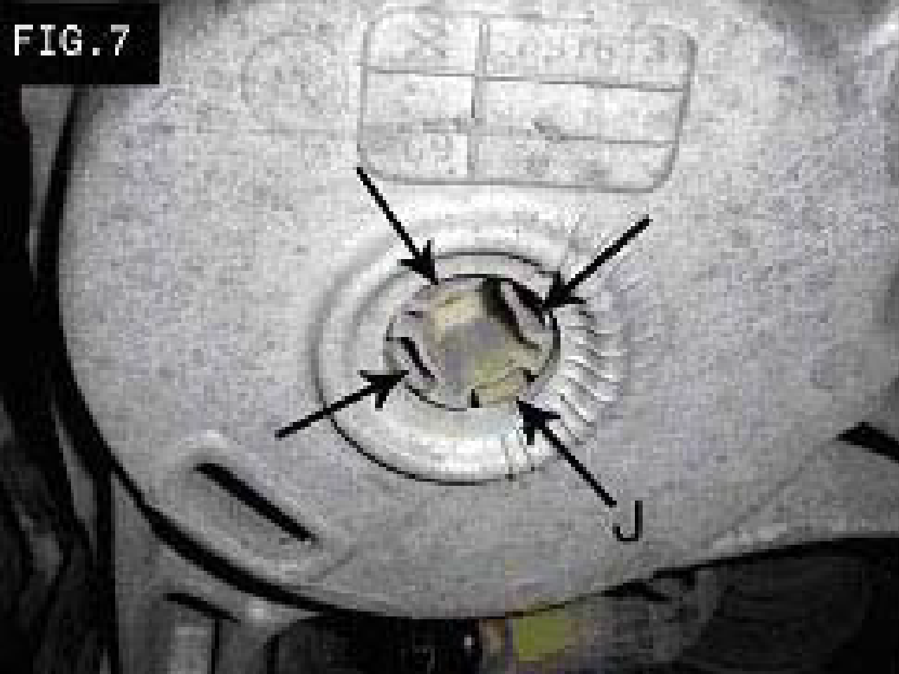
- (FIG. 6 and 7) Remove the air springs (G). Close in the centering tabs (J), on the bottom of the air springs and push the spring up.
- Rear:
- Verify that the height sensors and solenoids are disconnected from vehicle.
- Pull air lines and unused electrical lines into the trunk.
- Wrap wires and lines together in a loose bundle. Use the supplied wire tie-down to secure wires and line to existing wiring harness. CAUTION: Make sure the wires are away from all heat sources and moving parts.
- Inspect all original parts as removed for damage. Obtain replacements when necessary.
- Collect parts from the box labeled 99102. CAUTION: Be sure that the correct assembly sequence is followed.
- Assemble rear coil spring system:
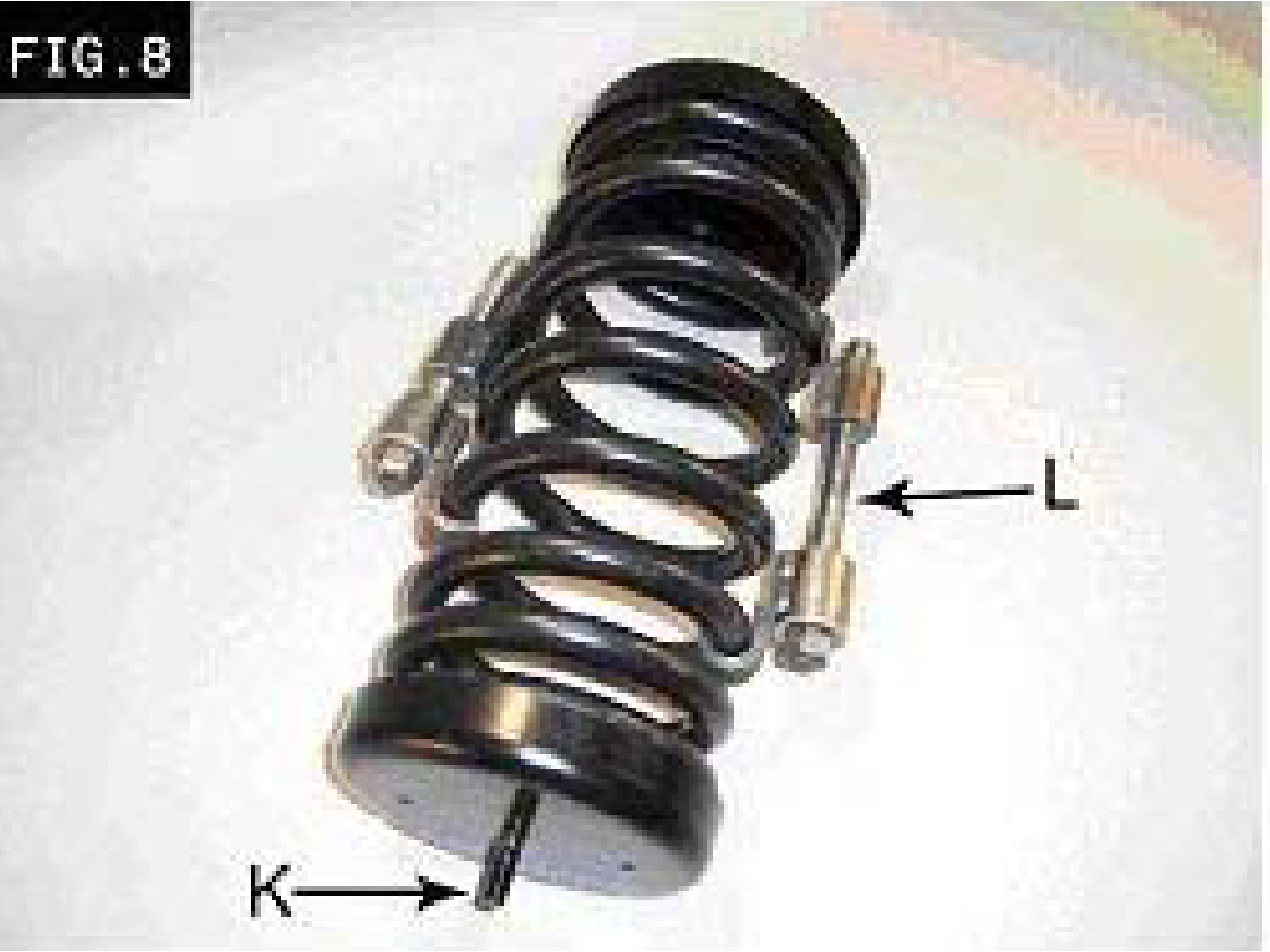
- Install a rubber cushion, retainer, and nut (found in the parts package) on the lower spring seat (K) (the seat with the longer stud.) Start the nut by hand.
- Place on isolator in each of the spring seats.
- Install the upper and lower spring seats on each spring (make sure to line up the isolator’s helix with the spring.)
- Use spring compressors (L) as much as needed.
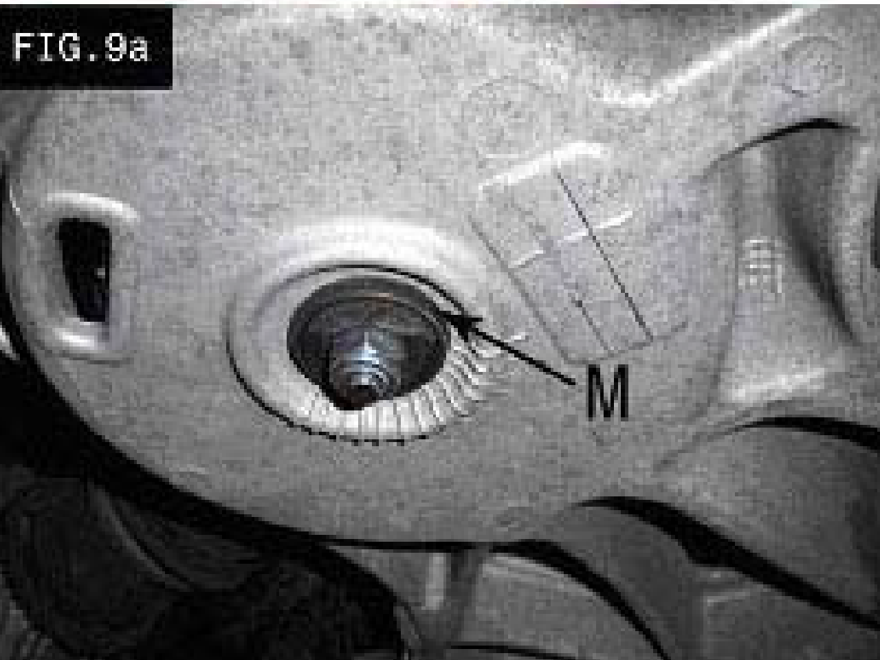
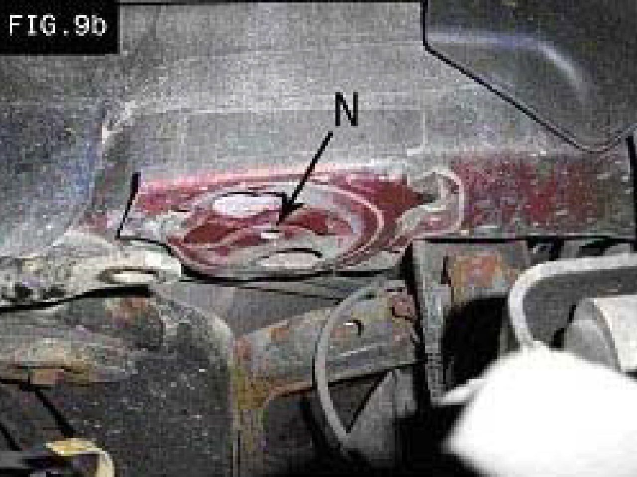
- (FIG. 9a and 9b) Install the rear coil spring assembly, starting with the lower seat. Make sure the rubber centering cushion is resting in and through the center opening (M). The shorter stud, on the upper seat, needs to rest in the upper centering hole (N).
- Install new rear shocks and tighten the upper mounting nuts.
- Reattach stabilizer bar link (H) to stabilizer bar. Torque Nut (W) to 7.5-10 ft-lbs (10-13 N-m). Recommended to replace this link if worn or damaged.
- Tighten the centering cushions nut until the rubber fills the opening.
- Replace the wheels and lower the vehicle.
- Check alignment of entire vehicle after installation, and adjust as necessary.
This part of the procedure relates to the disabling of the warning systems for the Air Ride Suspension. Failure to follow this part of the instruction will lead to visual and audible warning signals. (The vehicle is safe to drive without the following steps).
- Make sure engine is off and keys are not in the ignition.
- Ensure battery ground is disconnected.
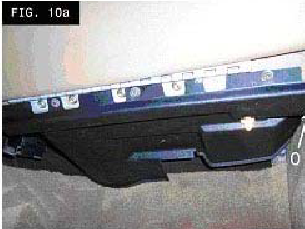
- Remove glove box and lower panel.
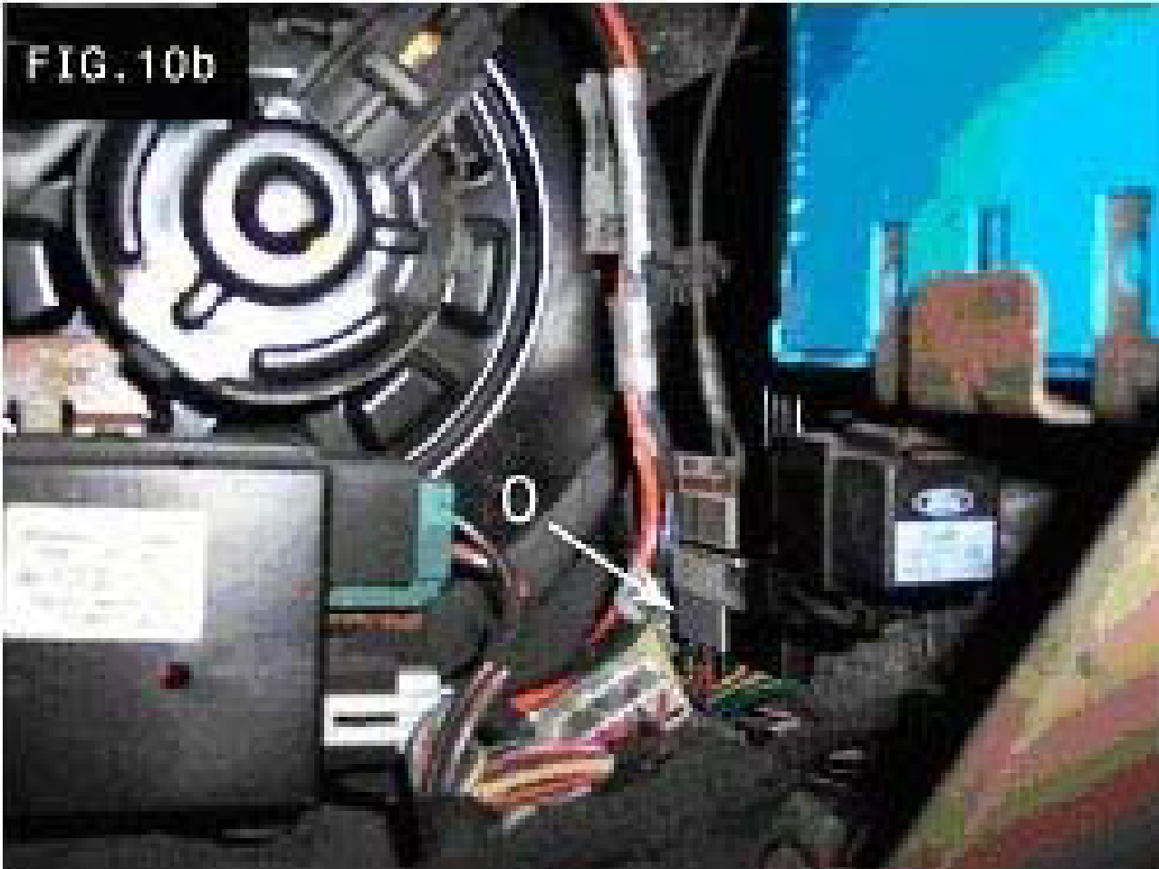
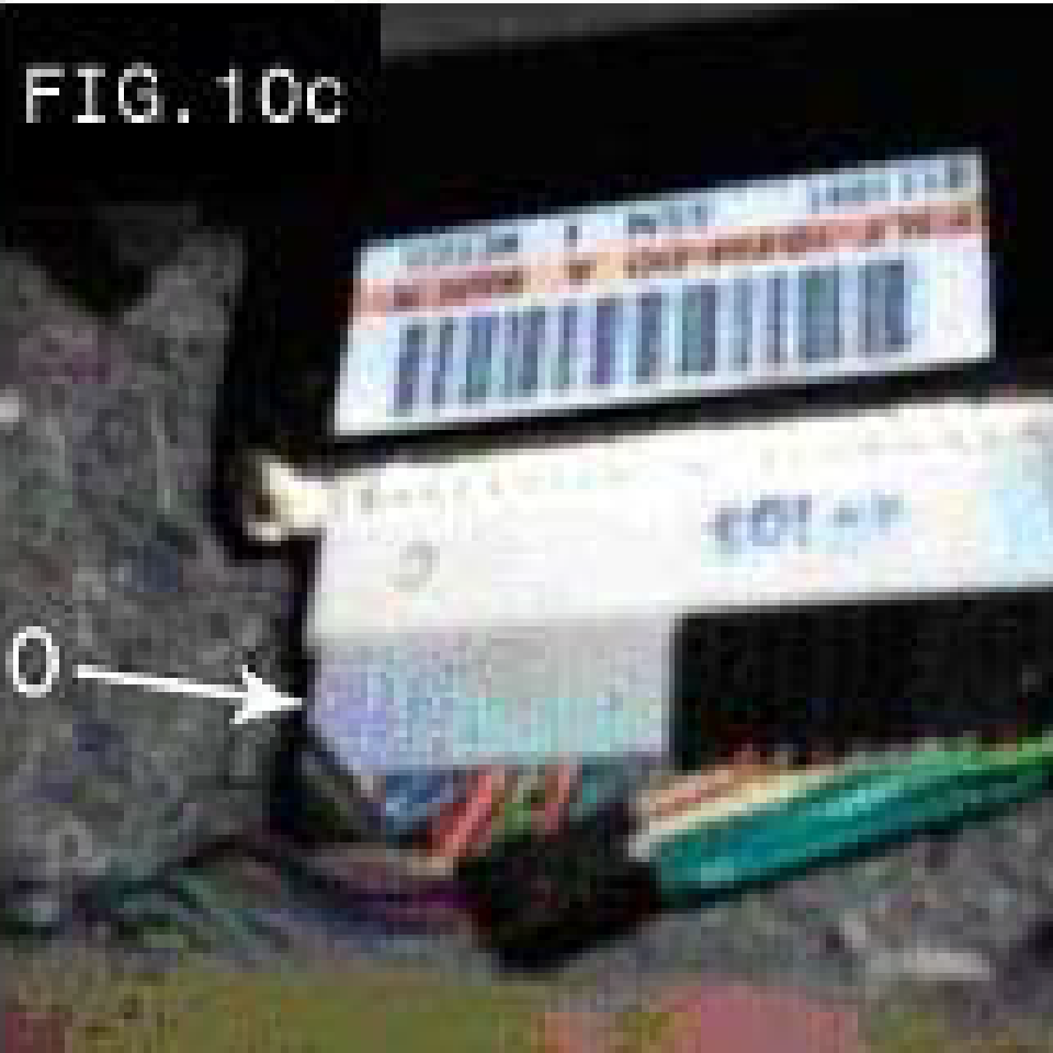
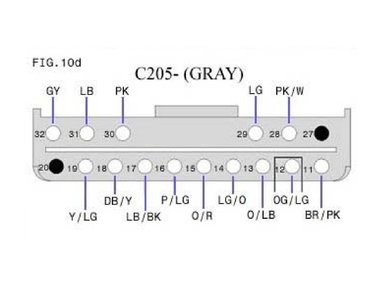
- (FIG. 10b, 10c, and 10d) Unplug the gray plug (O) from the module and cut the number 12 wire (FIG. 10d) (dark green and light green). This only deactivates the computer message on the dash. Tape both ends of the wire with electrical tape to keep them from contacting each other or anything else.
- Re-install the gray plug into the module and re-assemble the lower panel of the glove box.
- Reconnect the battery ground and turn the switch in the trunk back to “on” (A).