For Vehicles Originally Equipped with Air Leveling System:
- 2006-2003 Ford Expedition 2WD & 4WD
- 2006-2003 Lincoln Navigator 2WD & 4WD
- Read this instruction sheet and any instructions printed on the parts package carefully prior to removing the components from the vehicle.
- Do not grip the polished piston rod of a shock with any tool. Nicks or scratches will reduce the shock absorber’s service life.
- Part number on the shock or spring may differ from the part number on the carton. Contents are correct for the vehicle.
WARNING!
- Before servicing any vehicles equipped with original air spring suspension, turn off the "air suspension switch" located on the left panel in the rear cargo area.
- Do not attempt to remove the air spring from the suspension if it still contains air. Clear the air from the spring before servicing.
- If the shocks supplied are nitrogen gas pressurized, do not heat or open.
- Always wear safety glasses for eye protection.
- Use safety stands whenever a procedure requires you to be under a vehicle.
This kit replaces air leveling suspension on the vehicles listed above. This is a primary suspension, since this kit replaces the air spring system with conventional coil springs, ALL FOUR dampers must be changed. The kit is designed to provide a complete conversion of the suspension. The air pump system must be disengaged. Also includes the instructions to eliminate most of the electronic warning signals. There may be cases where the “reset” with the warning message system will need to depress after each start mode, since this will affect other information within the control module.
Ford Expedition and Lincoln Navigator systems are virtually the same for the suspension. However, the Navigator models do have some differences on the electrical logic which are affected by the suspension control module. Other items such as the ride height (kneeling) on the 4WAS system and retractable running boards.
Components in this kit are designed to replace worn or nonoperational original equipment parts on the vehicle, providing a conversion from air spring to conventional coil spring suspension.
This kit may be used for replacement on vehicles equipped with coil spring suspension, which is standard equipment on certain models.
If the air springs have failed, but the air pump is still functional, replacement air struts are available from the original equipment manufacture, which will not disable the air system.
The ride heights noted are after installation of the coil spring conversion. This is the same as a vehicle originally equipped with a conventional suspension. The ride height will be higher on most vehicles due to the curb/static versus normal driving/trim conditions for air suspension. Essentially, the height will increase by about 1 inch (25mm). More information can be found in the Ford Service Manual if necessary. Height will be approximately, as measured from centerline of wheel to lower edge of wheel molding.
FRONT – 20” to 20¼”
REAR – 20½” to 20¾”
If needed, you can refer to the Ford original equipment service manual for servicing the air spring air solenoid valves and for removal of the particular shock absorbers. This Instruction Sheet is a guideline and reference tool for the installation. Due to minor installation difficulty, it is necessary to follow the steps and methods detailed to ensure quality completion. Some of the installation steps may require the use of special tools designed for specific procedures.
Inspect all original parts as you remove them from the cartons for correct quantity and any potential damage. Obtain replacements where necessary.
Additional removal procedures are packaged with each damper assembly (within individual cartons).
This is a complete module assembly for removal and installation. Refer to installation instructions within the individual cartons of replacement unit.
- Prior to lifting the vehicle and removing its wheels, turn off the air suspension control switch, located on the left panel in the rear cargo area. Make sure that the ignition switch is in the OFF position.
- Raise vehicle at proper lift points. (Consult Ford Owners Manual if necessary) and make sure the vehicle is properly supported. Support the axle with a hoist or adjustable lift/stands. Remove wheel and tire assembly.
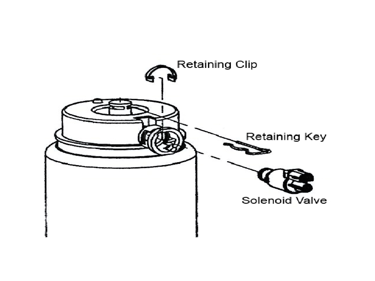
- Disconnect the electrical connector at the top of the strut module at the solenoid valve (Consult Ford Service Manual if necessary). Also, remove the air line by pushing on the small colored outer ring and pulling on the line simultaneously. To release the air from the air springs, remove clip from solenoid and rotate the solenoid valves counterclockwise to the first stop. This will allow the air in the spring and system to slowly escape. The solenoid may then be removed after all air has been exhausted. Mark location and retain this solenoid which be reinstalled on vehicle as noted under the conversion disable section. (Note: Provided the solenoid valves and air springs are still functional, these should be retained if the air system is ever to be reinstalled).
- Remove the nut and detach the steering tie rod end from the wheel knuckle. You should use the hex holding portion of the stud to prevent turning while removing the nut.
- To remove the strut assembly, remove the lower suspension bolt for the module, save bolt for reuse. Then remove the three (3) upper mounting plate nuts to frame. Do not remove the center nut which maintains the assembly of the module.
- Remove the old strut module from the vehicle.
- Install the new strut module, which has a coil spring. Installation essentially is reverse to the removal. This is the same module used for vehicles originally equipped with non leveling (air) suspension.
- Tighten the three (3) upper mounting plate nuts to 26 ft-lbs (35 N-m). Attach the lower mounting using the original bolt (replace if necessary). Tighten to 295 ft-lbs (400 N-m).
- Reattach the steering tie rod end, tighten to 111 ft-lbs (150 N-m).
- Reinstall the solenoid valves back into the position and plug in the electrical portion. It is not necessary to plug the air portion back into the solenoid. Use the provided cap (red cover) to cover the air line from debris. Using one of the provided bags, place the solenoid valve within and condense bag to remove air then tape closed with electrical tape (not provided). Secure this to the frame in an area not exposed to exhaust system, using the tie straps (provided) to prevent movement.
- Reinstall wheel and tire assembly, tighten nuts to 85 ft-lbs (115 N-m).
This is a similar procedure for the majority as the FRONT removal. The air suspension control switch should remain off, located on the left panel in the rear cargo area. Make sure that the ignition switch is in the OFF position.
- The vehicle should still be raised at proper lift points and properly supported. Remove wheel and tire assembly.
- Disconnect the electrical connector at the top of the strut module at the solenoid valve (Consult Ford Service Manual if necessary). Also, remove the air line by pushing on the small colored outer ring and pulling on the line simultaneously. To release the air from the air springs, remove clip from solenoid and rotate the solenoid valves counter-clockwise to the first stop. This will allow the air in the spring and system to slowly escape. The solenoid may then be removed after all air has been exhausted. Retain this solenoid to be reinstalled on vehicle as noted under the conversion disable section. Note: Provided the solenoid valves and air springs are still functional, these should be retained if the air system is ever to be reinstalled.
- To remove the strut assembly, remove the lower suspension bolt for the module, save bolt for reuse. Then remove the three (3) upper mounting plate nuts to frame. Do not remove the center nut which maintains the assembly of the module.
- Remove the old strut module from the vehicle.
- Install the new strut module, which has a coil spring. Installation essentially is reverse to the removal. This is the same module used for vehicles originally equipped with non leveling (air) suspension.
- Tighten the three (3) upper mounting plate nuts to 26 ft-lbs (35 N-m). Attach the lower mounting using the original bolt (replace if necessary). Tighten to 350 ft-lbs (475 N-m).
- Reinstall the solenoid valves back into the position and plug in the electrical portion. It is not necessary to plug the air portion back into the solenoid. Use the provided cap (red cover) to cover the air line from debris. Using one of the provided bags, place the solenoid valve within and condense bag to remove air then tape closed with electrical tape (not provided). Secure this to the frame in an area not exposed to exhaust system, using the tie straps (provided) to prevent movement.
- Reinstall wheel and tire assembly, tighten nuts to 85 ft-lbs (115 N-m).
This part of the procedure relates to disabling the warning systems for the Air Ride Suspension. Failure to follow this part of the instruction will lead to visual and/or audible warning signals. The signals will not harm the operation of the vehicle after the coil spring conversion, but may be an annoyance. There may be cases where the “reset” with the warning message system will need to depress after each start mode, since this will affect other information within the control module.
Lincoln Navigator vehicles built prior to February 3, 2003 use a solid-state relay for the air suspension compressor motor. The control line from the module is grounded to energize the relay.
Both Navigator and Expedition vehicles equipped with air suspension built since February 3, 2003 utilize a mechanical relay for the compressor motor. The control line from the module is grounded to energize the relay. This relay is located on the compressor bracket just above the compressor attachment to the radiator support on the right side.
- Make sure engine is off and keys are not in the ignition.
- Ensure battery ground is disconnected.
- Turn OFF the air suspension switch located above the passenger side front kick panel or under dash below the glove box, if not previously done.
- If not already completed, reinstall the solenoid valves back into the position and plug in the electrical portion. It is not necessary to plug the air portion back into the solenoid. Use the provided cap (red cover) to cover the air line from debris. Using one of the provided bags, place the solenoid valve within and condense bag to remove air then tape closed with electrical tape (not provided). Secure this to the frame in an area not exposed to exhaust system, using the tie straps (provided) to prevent movement. This is required to complete circuit on system.
- Unplug the Air Pump Connector C1179 located behind the right hand head light near the air suspension pump.
- Remove the Air Suspension Relay C1198, located on the right hand side below the head light on the radiator support.
- No additional items are to be completed with the Control Module, as this is required to maintain steering inputs to the EVO Steering Module and ride information.
- If the vehicle has instrument panel having bulb system, to disarm the “Check Air Suspension” light, remove the instrument cluster then unplug the light or remove the bulb from this warning lamp. Reinstall the instrument cluster. If this has a message center with the solenoids reinstalled, this should eliminate the “CHECK SUSPENSION” message.
- Turn back ON the air suspension switch located above the passenger side front kick panel or under dash below the glove box. This MUST be in the ON position to allow the EVO Steering and other items to continue functioning.
- If the message is continued to be displayed, due to the logic with the Suspension Control Module depress the “reset” button on dash to remove the warning message. You may need to perform this sequence of depressing the “reset” button the after each start mode, since this will affect other information within the control module.