For Vehicles:
- 2006-2002 Cadillac Escalade
- 2006-2002 Cadillac Escalade EXT
- 2006-2003 Cadillac Escalade ESV
- 2006-2002 Chevrolet Tahoe, Autoride Z55 suspension package
- 2006-2002 GMC Denali (Yukon)
- 2006-2002 GMC Yukon, Autoride Z55 suspension package
- Read this instruction sheet and any instructions printed on the parts package carefully prior to removing the components from the vehicle.
- Do not grip the polished piston rod of a shock with any tool. Nicks or scratches will reduce the shock absorber’s service life.
- Part number on the shock or spring may differ from the part number on the carton. Contents are correct for the vehicle.
WARNING!
- Before servicing these vehicles equipped with original air leveling shocks, turn off the “air suspension switch” or “remove the power source (fuse) to the air pump.
- Do not attempt to remove the air shock from the suspension if it still contains air. Clear the air from the spring before servicing.
- If the shocks supplied are nitrogen gas pressurized, do not heat or attempt to open. Always wear safety glasses for eye protection.
- Use safety stands whenever a procedure requires you to be under a vehicle.
This kit described in these instructions replaces the front electronic shock absorber and rear electronic air shock absorbers. The components will replace the electronic portion of the system on the vehicle, but will still maintain the air leveling portion.
The FRONT is a passive replacement of the original shock absorber. All components for the installation are provided. The parts package with the “resistor” will maintain the electrical circuit to eliminate any “service ride control” message caused by the multi stage electronic control within the shock absorber.
The REAR is a passive replacement of the original air leveling shock absorber. This replacement passive air shock will still provide air leveling, but will eliminate the electronic portion of the system, provided the air pump is still functional. All components for this installation are provided. The parts package with the “resistor” will maintain the electrical circuit to eliminate any “service ride control” message caused by the multi stage electronic control within the shock absorber.
If the air leveling pump is NOT functional, this will need to be repaired or replaced. If this is not corrected, the same “service ride control” message will occur.
This installation can be completed if the air pump is eliminated by obtaining and installing a manual fill air line kit AK29 (not provided within conversion kit), which will abort the pump leveling system. The pump system will need to disconnected, which will remove the error from the message center.
Recommend that installation of all shock absorbers be completed first, then complete all electrically conversions/installations afterward.
If needed, you should refer to an original equipment service manual for removal of other items outside of servicing these shock absorbers. This instruction sheet is a guideline and reference tool for the installation. Due to minor installation difficulty, it is necessary to follow the steps and methods detailed to ensure quality completion.
Some of the installation steps may require the use of special tools designed for specific procedures. The following tools and supplies are recommended for proper installation of this system:
- General Motors Service Manual.
- Torque Wrench (100 ft-lbs).
- Hydraulic Floor Jack.
- Heavy Duty Floor Jack Stand.
- Assorted ½” Drive Ratchet and Sockets.
- Assorted Combination Wrenches.
- Large Adjustable Wrench.
- Volt/Ohm Meter.
- Poly Electrical Tape.
- Heat Gun for shrink tube.
- Wire Cutter and Crimpers.
- Safety Glasses/Stands.
Inspect all parts as you remove them from the cartons for correct quantity and any potential damage. Obtain replacements where necessary.
- Make sure that ignition switch is in the OFF position. Raise vehicle at recommended lift points and remove wheels (consult GM Owners or Service Manual if necessary) and make sure the vehicle is properly supported.
- Remove the lower mounting bolts to the shock from lower control arm and save for reuse.
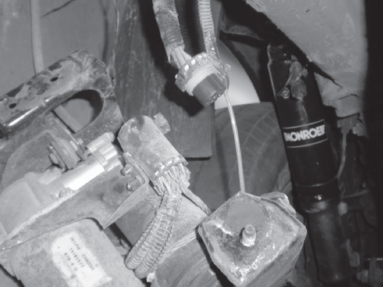
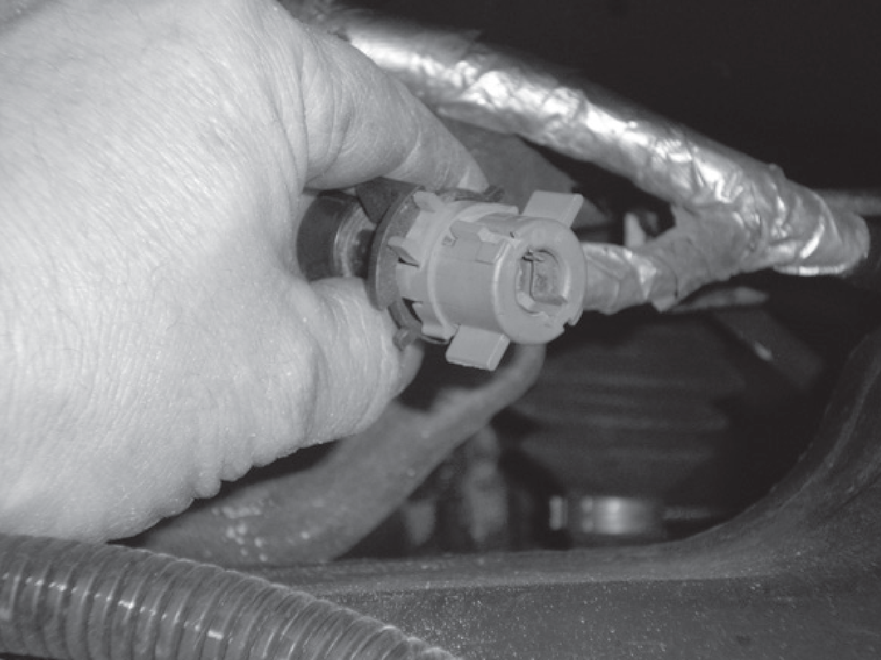
- Disconnect the electrical connector from the top or stem end, by rotating the grey portion counter clockwise of the black portion. This unlocks the connector from the stem and will be able to pull straight upward to remove.
- Once connector is removed, the shock absorber mounting nut may be removed. All new components for upper end will be provided, the entire shock assembly can now be removed from the vehicle.
- The new shock absorber assembly can now be installed. Tighten the upper stem components until the cushion is slightly bulged (approximately 3/4 of original height. Install lower mounting bolt through clevis, reusing original bolt or obtain a new replacement (not provided). Tighten bolt to 42 ft-lbs (57 N-m).
- Repeat for opposite side.
- The electrical connectors will now need to have a resistor installed (provided). Refer to the instructions within the part package for this installation. The use of a heat gun needed at this point for insulation of the electrical connections. Recommended that the entire vehicle shock absorbers first, then install resistor kits on all four corners for consistency.
- Again, make sure that ignition switch is in the OFF position. Raise vehicle at recommended lift points and remove wheels (consult GM Owners or Service Manual if necessary) and make sure the vehicle is properly supported.
- Support the axle prior to removal of any bolts, suggest completing one side at a time.
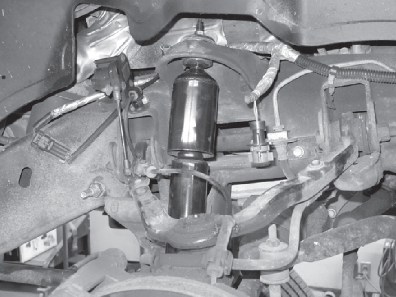
- Remove the air line from the shock by separating the clip and pull straight out. Prevent dirt from entering the end of this air line.
- Disconnect the electrical connector for the electronic ride control from the rearward portion of the shock.
- Remove the upper and lower mounting bolts, save for reuse. Remove shock absorber assembly from vehicle.
- The new shock absorber assembly can now be installed. Tighten bolt to 42 ft-lbs (57 N-m).
- Reinstall the air line to the shock. There may be a protective cap over the fitting, so remove first. The original air fitting will attach by pushing directly on to fitting. Air will need to added to shock prior to vehicle being set to static height.
- Repeat for opposite side.
- Once both shocks are install, air will need to added to shocks prior to vehicle being set to static height. The leveling valve at the control are can be disconnected to move manually and by turning on ignition and moving the valve are upward the pump should activate. Only a small amount of air needs to inflate the air sleeve to prevent folding inside of dirt shield.
- The electrical connectors will now need to have a resistor installed (provided). Refer to the instructions within the part package for this installation. The use of a heat gun needed at this point for insulation of the electrical connections. Recommended that the entire vehicle shock absorbers first, then install resistor kits on all four corners for consistency.
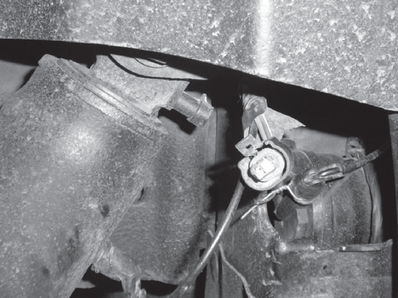
As noted previously, a resistor is installed (provided) on all four corners. Refer to the instructions within the part package for this installation. This part of the procedure relates to disabling the warning systems for the Electronic Ride Control Systems. Not completing this part of the instruction will lead to visual and/or audible warning signals or messages. However this will NOT harm the operation of the vehicle. The message or warning may be an annoyance after the conversion, but the suspension is fully operational.
This part of the procedure relates to disabling the warning systems for Air Compressor Pump Control. This is ONLY to be completed if conversion has been completed and no longer plan on using the on-board leveling compressor pump. This pump then needs to be disabled. Manual air fill lines will need to be utilized. Not following this part of the instruction will lead to visual and/or audible warning signals or messages, again which will not harm the operation of the vehicle. The message or warning may cause annoyance after the conversion, but the suspension is fully operational. If needed, you can refer to the original equipment service manual for servicing the air leveling system using a scan tool. Several codes will detect air system is still functional or indicate items in question. The scan tool can also reset any error codes causing message lights or message center to be illuminated.
- If conversion has been completed to no longer use the on-board leveling compressor pump, this needs to be disabled. Remove the splash shield to gain access to the pump. Unplug the pump from the electrical system.
- Refer to the owner’s manual or electrical circuit manual for location of fuse block for specific vehicle, either in the engine or trunk compartments.
- Locate the dedicated fuse within the fuse block, typically it is a 30 or 50 amp. Remove this fuse to eliminate operation of the compressor pump if not unplugged and electrical source.