For Vehicles:
- 1992-1989 Cadillac Allante (with SSD or Speed Sensitive Damping)
- 1993-1991 Cadillac Deville (with CCR or Computer Command Ride)
- 1995-1994 Cadillac Deville (with SSD or Speed Sensitive Damping)
- 1996 Cadillac Deville (with SSS or Speed Sensitive Suspension)
- 1991 Cadillac Eldorado / Seville (with Computer Command Ride or CCR)
- 1992 Cadillac Eldorado / Seville (with SSS or Speed Sensitive Suspension)
- 1993 Cadillac Eldorado / Seville
- 1995-1994 Cadillac Eldorado / ELS (with SSS or Speed Sensitive Suspension)
- 1995-1994 Cadillac Seville / SLS / STS (with SSS or Speed Sensitive Suspension)
- Read this instruction sheet and any instructions printed on the parts package carefully prior to removing the components from the vehicle.
- Do not grip the polished piston rod of a shock with any tool. Nicks or scratches will reduce the shock absorber’s service life.
- Part number on the shock or spring may differ from the part number on the carton, contents are correct for the vehicle.
WARNING!
- Before servicing any vehicles equipped with original air spring suspension, turn off the "air suspension switch" in the trunk area.
- Do not attempt to remove the air spring from suspension if still containing air. Release the air from the spring before servicing.
- If the shocks supplied are nitrogen gas pressurized, do not heat or open.
- Always wear safety glasses for eye protection.
- Use safety stands whenever a procedure requires you to be under a vehicle.
These kits described replacement of “electronic” or “active” struts and shocks. The components will replace these to a “passive” system on the vehicle. Due to the variation of systems between model years, use the appropriate instruction sections for front or rear as needed, for removal and installation.
The FRONT original electronic adjustable will use a passive or non-electronic replacement strut. All components for the strut assembly except the spring are provided (unless otherwise specified). The original coil spring will be reused for this assembly. It is suggested that a new stabilizer bar link be obtained for reinstallation.
The REAR original electronic adjustable may either be replaced with passive air shock to provide air leveling (if the air pump is still functional) or a conversion replacement passive coil spring shock which provides the necessary lift to maintain ride height without the use of air. Both versions will allow you to abort the electronic ride control system from the vehicle.
The kits are designed to provide a conversion of the suspension, along with disengagement of the pump system. This conversion contains the necessary instructions to eliminate the electronic warning signals on some models. Some additional components may be required for certain vehicle.
If needed, you may refer to an original equipment service manual for servicing the electronic solenoid valves. This instruction sheet is a guideline and reference tool for the installation. Due installation difficulty, it is necessary to follow the steps and methods detailed to ensure quality completion. General Motors has a technical service bulletin TSB 00-03-11- 001 (dated August 2000) with details the factory recommended procedure for installation of “passive” struts to replace the original “active/electronic” struts.
Inspect all parts as you remove them from the vehicle for any potential damage. Obtain replacements where necessary.
- Make sure that ignition switch is in the OFF position. Open hood to locate the upper strut mounting nuts, this may have a plastic cover which must be removed. Raise vehicle at recommended lift points (consult GM Owners or Service Manual if necessary) and make sure properly supported. Prior to removal of the wheels, mark one of the lugs to wheel for original orientation for reinstallation, and then remove.
- Remove the lower mounting bolts that attaches strut to spindle carrier and save for reuse. Support the half shaft; do not allow this to be disengaged from transaxle. Remove the stabilizer bar link from the strut and save nut for reuse. Remove the attachment bolt from the bracket for the brake line and ABS wire and save for reuse. Be sure you do NOT stretch brake lines or ABS sensor wires.
- Disconnect the electrical connector for the electronic ride control is near front area of the vehicle. This may involve removal of the front portion of the inner fender splash shield to gain access to this connector. To disconnect, the locking tabs will have to be opened to separate the connector. This should not be damaged as the wire and solenoid valve will be used later to eliminate warning message.
- Once all components on the lower end are disconnected, the upper retaining nuts may be removed and the entire strut assembly removed from vehicle.
- The strut assembly can be disassembled. Place identification marks on the components for alignment at reassembly. Closely examine the orientation of old components for reassembly of new items. Compress the spring with a suitable spring compressor to relieve tension. Once spring is loose from the seats, the center nut within the upper mounting may now be removed. Then relieve the spring compressor (if necessary dependent upon the type of compressing tool). Remove the strut and upper mounting (if the spring is retained). Only the spring is required for reinstallation. All old components from this assembly can be discarded after the solenoid valve has been removed. The solenoid valve will be reused on the vehicle to complete electrical circuit.
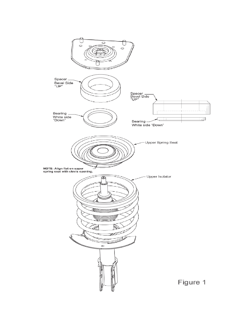
- (FIG. 1 above) There are new components for reinstallation provided in kit. The new strut provided can be used on either side of the vehicle, since it has an unhanded stabilizer bar bracket. If the rod is compressed, turn the rod counterclockwise to unlock for extension, if nitrogen charged. There are applications that the strut is not nitrogen charged, simply pull rod out to extend. Install the new jounce bumper/dirt shield onto the rod. Assemble the new components in correct order being upper spring seat, rubber spacer, bearing (white side down) and upper mounting. Note that the new rubber spacer may appear to be thicker and different shape than original component. The original has been distorted by the age and weight of the vehicle. The new component will become similar shape after time. Assembly Install the new strut within the spring and attach the upper mounting components using the new provided rod post nut. Torque to 50-55 ft-lbs (67-74 N-m).
- (FIG. 1 above) Reinstall the completed strut assembly on the vehicle. This is the reverse procedure used for disassembly from step 2. Attach upper mounting using the three new nut provided to mounting plate studs, torque to 18-22 ft-lbs (24- 29 N-m). Reattach the lower mounting bolts, torque to 73- 78 ft-lbs (98-107 N-m). Reattach the bracket for the brake line/ABS; the anti-rotation tab on the bracket may have to be bent to provide clearance for bolt.
- Reattach the stabilizer bar link to the strut. If this is damaged, obtain a new original equipment component. Due to the tapered end design of the link, use the provided tapered ID washers (in parts package) to allow for tight fit of link to strut bracket. These washers provide the similar thickness of the original strut bracket. Tighten nut to 25-29 ftlbs (34-39 N-m).
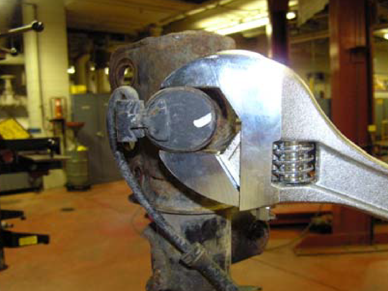
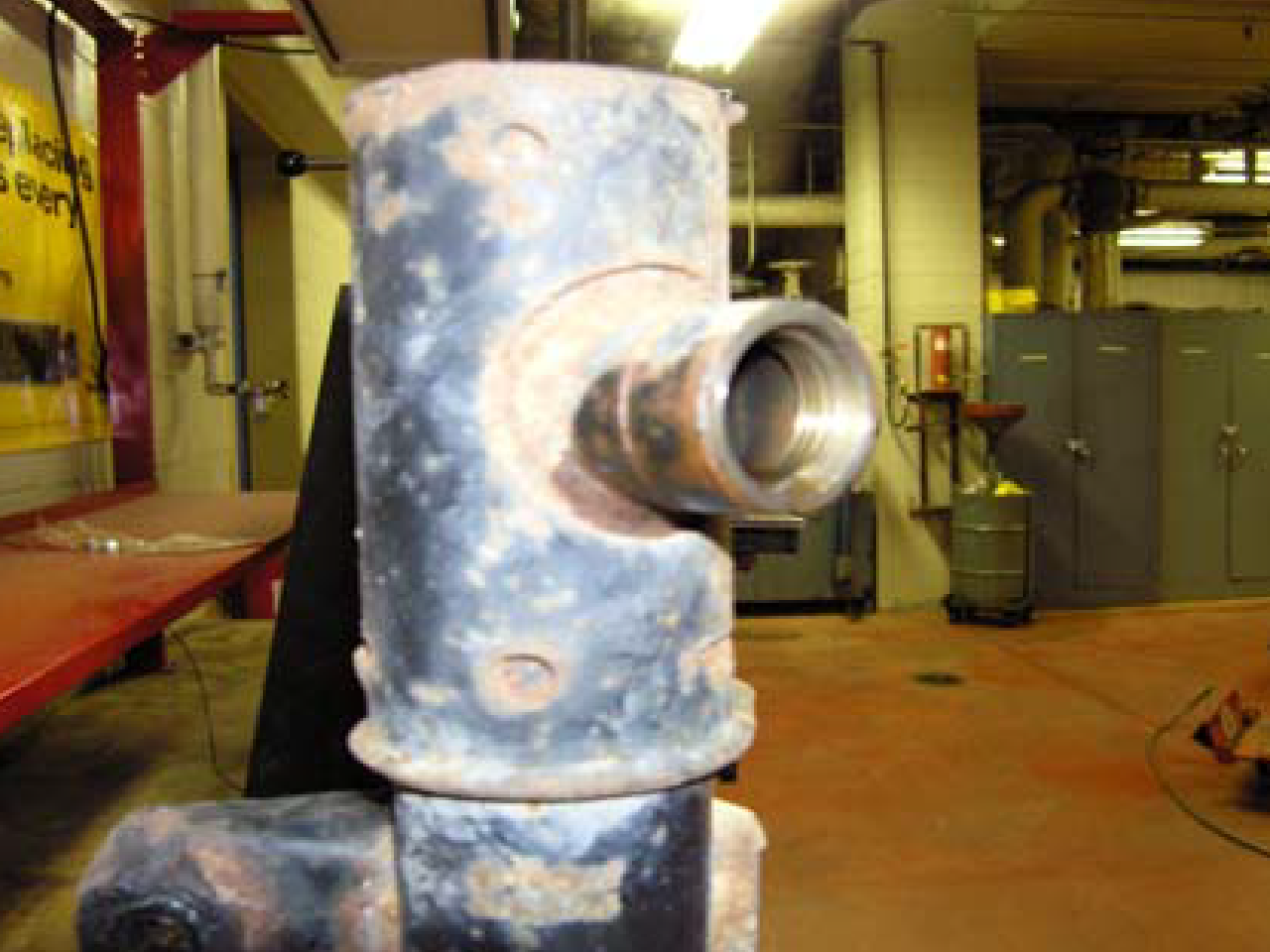
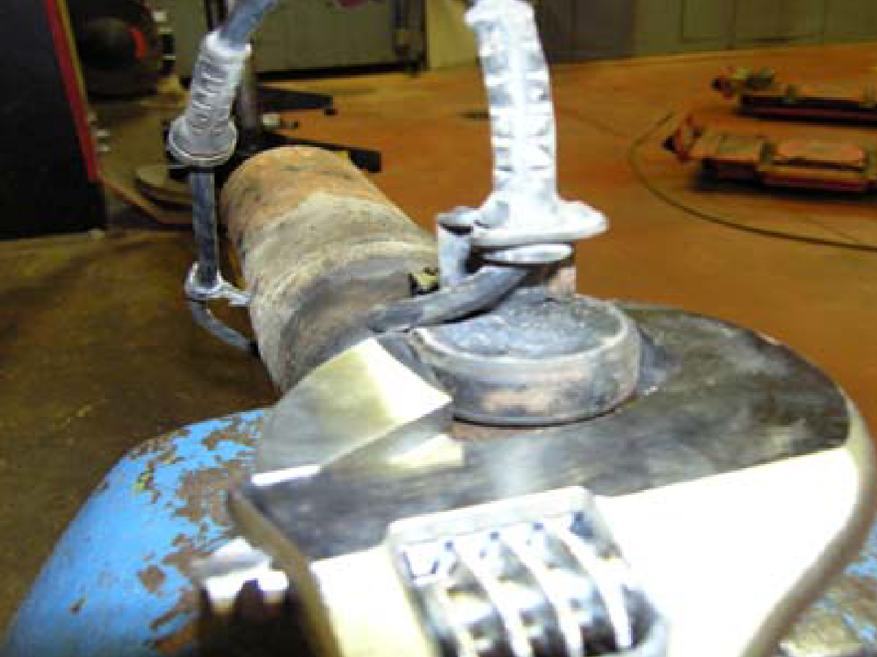
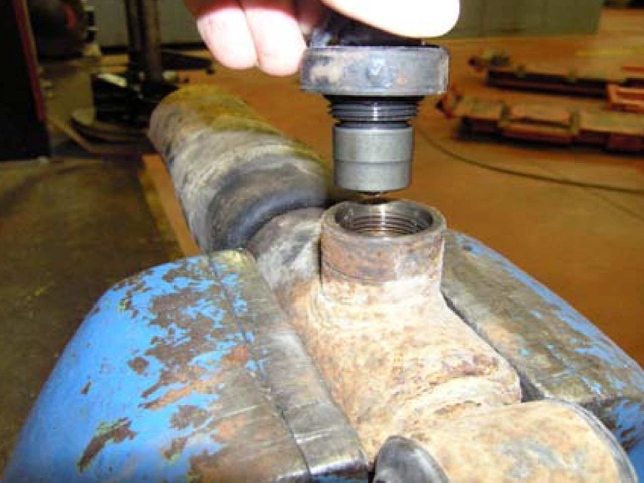
- (FIG 2, FIG 3) After the new strut assemblies have been installed on vehicle, go back to the original struts and retrieve the solenoid valves. These need to be removed and reattached to connector for circuit completion. Secure the old strut into a vise so the valve in up or on top. This is required to retain oil in strut once removed. By using a large adjustable wrench to grip the two flat areas of the valve, rotate counter-clockwise to unscrew the valve. There may be a slight exhaust of nitrogen gas once seal is broken. The original strut must have the oil drained using proper procedures for recycling and collection of oil. Strut can then be discarded in normal metal salvage.
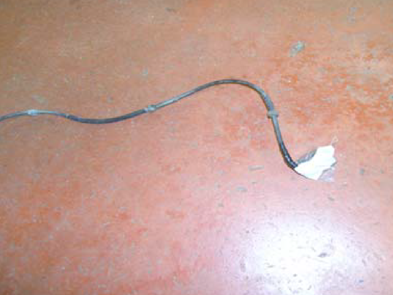
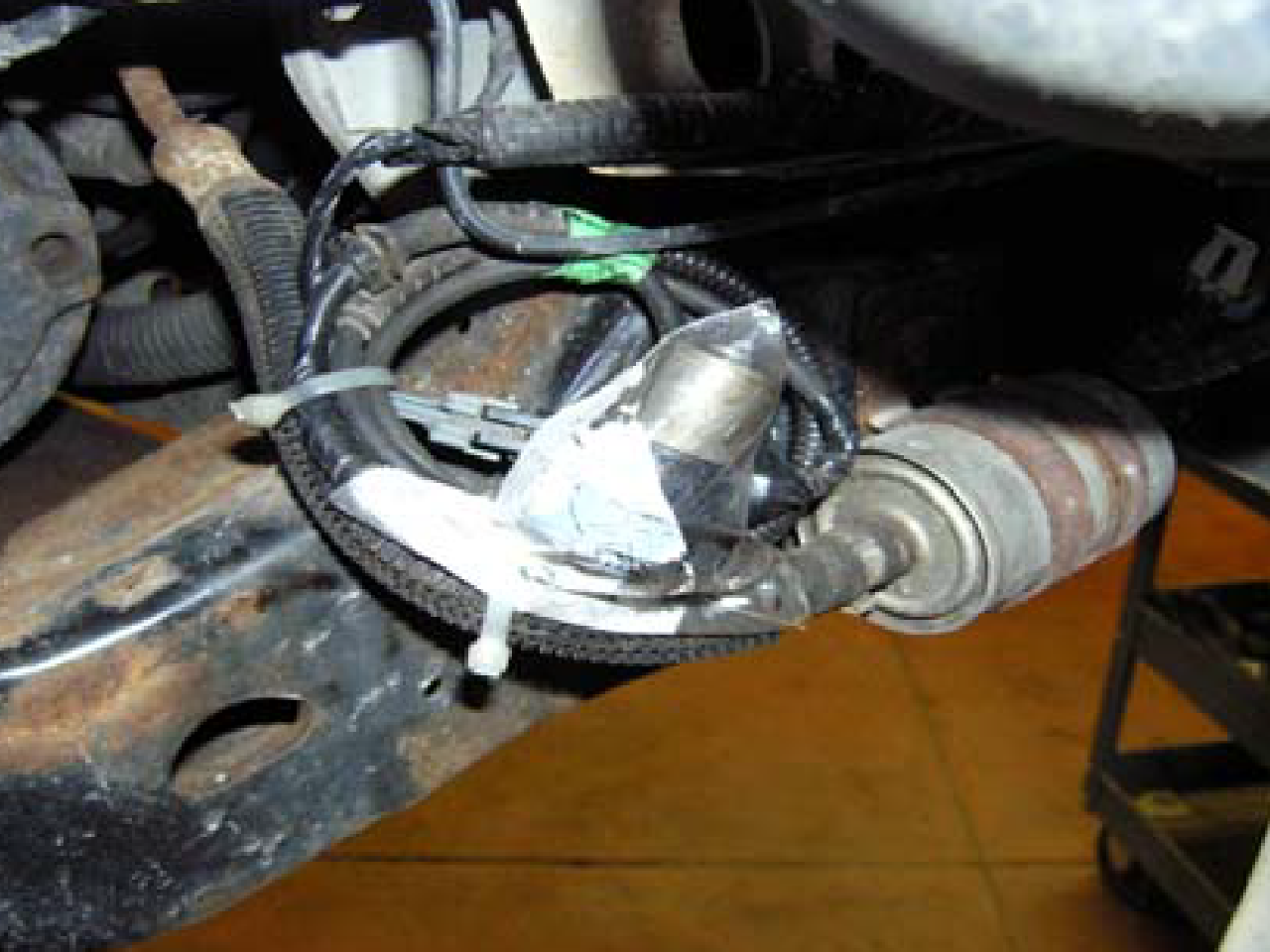
- (FIG 4, FIG 5) Once the valves removed, clean majority of oil off, not necessary to wash with solvent. Place valve in one of the provided poly bags, leaving the wire connector outside. Seal the bag with electrical tape around the wire. The entire bagged valve and harness can then be reattached to the connector. Secure the package to the frame or body area near the connector. This valve completes the circuit, which should avoid any warning message for “service ride control”.
- Reinstall all splash shields removed for access.
- Reinstall the wheel assembly, torque lug nuts to 72-75 ft-lbs (97-102 N-m). Entire procedure should be used for the opposite side of the vehicle.
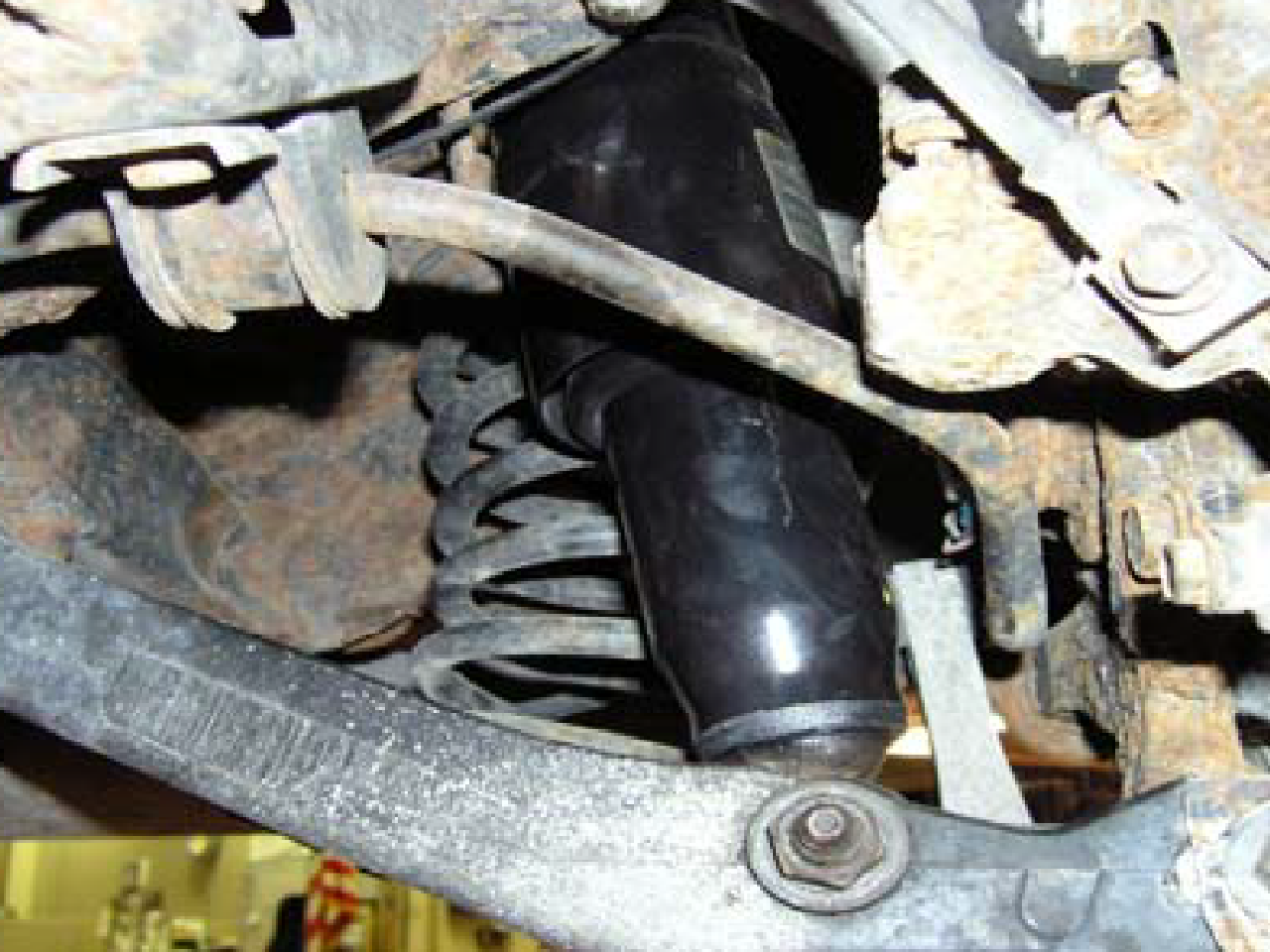
Note: The installation of all new components on the front can result in the vehicle ride height being increased by approximately ½ inch. Settling will occur over a short period of time. With the installation of rear dampers also, the overall vehicle should be similar.
- Again, make sure that ignition switch is in the OFF position. Raise vehicle at recommended lift points (consult GM Owners or Service Manual if necessary) and make sure properly supported. Prior to removal of the wheels, mark one of the lugs to wheel for original orientation for reinstallation, and then remove.
- Remove the lower mounting bolt(s) from lower control arm and save for reuse. The lower control arm may need to be supported to allow removal this bolt(s). Remove the air line from the shock by separating the clip and pull straight out.
- Disconnect the electrical connector for the electronic ride control. This connection is located on the rearward side of the suspension cradle. Mark this solenoid near the damper to identify left or right side. This connector is similar to the front suspension. To disconnect, the locking tabs will have to be opened to separate the connector. This should not be damaged, as the wire and solenoid valve will be used later to eliminate warning message.
- Disconnect the upper retaining nut to remove the entire shock assembly from the vehicle.
- The new shock can be used on either side of the vehicle. Use the provided retainers and cushions for the upper mounting contain in the parts package. The pilot contained on the cushion should be centered within the upper mounting hole. Tighten the nut on the cushion until the cushion is approximately the same size as the retainer. This mounting stem does not have a positive stop to torque, so approximately four threads will be exposed when tightened correctly.
- (FIG 6, FIG 7) After the new shock installed, go back to the original shock and retrieve the solenoid valves. These are to be removed and reattached to connector for circuit completion. This is same procedure as completed with front strut (steps 9 and 10). Secure the old shock in a vise so the valve is up or on top. This is required to retain oil in strut once removed. By using a large adjustable wrench to grip the two flat areas on the valve, rotate counter-clockwise to unscrew the valve. There may be a slight exhaust of nitrogen gas once seal is broken. The original shock must have the oil drained – using proper procedures for recycling and collection of oil. Shock can then be discarded in normal metal salvage.
- (FIG 4, FIG 8) Once the valves removed, clean majority of oil off, not necessary to wash with solvent. Place valve in one of the provided poly bags, leaving the wire connector outside. Seal the bag with electrical tape around the wire. The entire bagged valve and harness can then be reattached to the connector. Secure the package to the frame or body area near the connector. This valve completes the circuit, which should avoid any warning message for “service ride control”.
- Reattached the lower mounting bolt, torque to 55-61 ftlbs (74-82 N-m). The lower control arm may have to be lifted to allow for bolt installation.
- If installing the air shock version, reattach the original air line back to fittings. To refill with air, both sides must have the air shocks installed. While vehicle is still on jack or lift, the leveling valve can be manually operated to fill shock with air. Remove actuator rod from leveling valve, rotate arm upper, so system is signaled to run the pump. The ignition key must be turned on for this to operate. Running the pump for approximately two minutes should provide sufficient air to inflate air sleeves, which is required before the shock is cycled. Turn ignition key to off. Reattach the actuator rod back the leveling valve. Once the vehicle is placed on ground, the system should cycle correctly.
- If installing a coil spring conversion shock, tape off the air fitting and secure to frame cradle. The air system will be disconnected by removing the fuse to eliminate pump. The coil springs will provide support, however the leveling function will not be retained. Vehicle ride height may be slightly high at rear suspension with the shock (approximately ½ inch). Some settling or lowering will occur over time.
- Reinstall the wheel, torque lug nuts to 72-75 ft-lbs (97- 102 N-m). Entire procedure should be used for the opposite side of the vehicle.
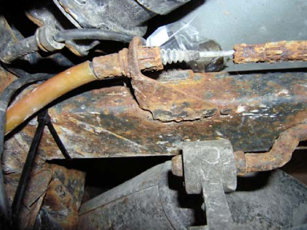
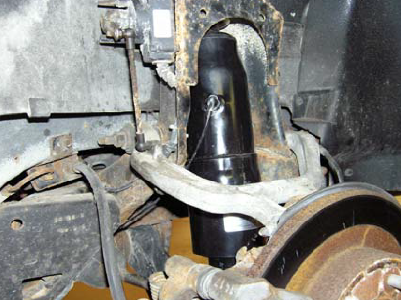
This part of the procedure relates to disabling the warning systems for the Electronic Ride Control Systems. Not following this part of the instructions will lead to visual lights, audible warning signals or messages which will not harm the operation of the vehicle. The message or warning may be an annoyance after the conversion, but the suspension is fully operational. This procedure differs for the specific year and model, which have different disabling methods as noted below.
- Normal Elimination of Warning Message with Speed Sensitive Damping or SSD: Provided that the solenoid valves are retained on the vehicle from the original strut or shock, the message center should not illuminate. If it does, then potentially an air pump operation issue may be affecting this condition. Refer to the Air Pump section below. The solenoid valves need to be used to maintain circuit resistance. If required a 2.2 ohm resistor may be used in place of these valves, available as parts package part number P01510 (which may be purchased separately). A resistor kit parts package must be used for each connector (or each corner of the vehicle), by cutting the connector and attaching across the two wires by crimp or soldering in place. Use the provided shrink wrap tubing or tape to protect electrical connection and prevent corrosion.
- Optional Temporary Elimination of Warning Message: Most of these vehicles have incorporated a reset button on the dash for this message center. If this is pushed once the message is illuminated, the message will be temporarily eliminated. Once the ignition is shut off and then restarted, this message will reappear. Thus message reset will have to be pushed each time circuit is broken. This reappearance and reset sequence will have to be completed approximately 15 times for the system to learn the setup. Some vehicles model years will require the computer control module to be reset using as diagnostic programmer to turn off the message.
- Permanent Elimination of Warning Message: Refer to the methods for specific year and models per the GM TSB 00-03- 11-001 (August 2000) and Service Manual pages 8A-43-0 (Deville) and 8A-43-14 (Deville, Eldorado, Seville). Additional components to allow for this permanent removal of the electronic message warnings may be needed; this component is NOT provided with this kit. This requires a modification of wiring harshness and installation of relay required to the control module for the suspension. A simple standard automotive 12- volt relay and standard blade crimp connectors (obtained at an automotive supply store). Or you can obtain GM part number 12193601 relay and p/n 15306045 connector. Directions and control module locations are noted in the steps below.
1991 Cadillac Eldorado / Seville (with Computer Command Ride or CCR):
Per the GM TSB 00-03-11-001 (August 2000), set the BCM override value “BS09” to “0” by using the Wanner and Cooler buttons. Store this value by pressing the “Econ” button on the Climate Control Panel and Instant Econ button on the Fuel Data Driver Information Center for approximately 5 seconds. The new value will be stored even though the indicator does not flash. Remove the key from the ignition, and then disconnect both battery cables. Once disconnected, touch the two cables together and hold for approximately 5 seconds. This will discharge the capacitors and allow system to perform properly when the battery cables are reconnected. Reminder: after this procedure, the clock and radio stations will need to be reset due to this disconnection of the power source.
1992 Cadillac Eldorado / Seville (with Speed Sensitive Suspension or SSS):
Per the GM TSB 00-03-11-001 (August 2000), observe and record the IPC override “IS08” displayed value, use the climate control Cooler button to decreased the value displayed for “IS08” by 8 points. To store the new value, press and hold the “Econ” and “Front Defrost” buttons until the new value flashes on and off.
1993 Cadillac Eldorado / Seville (with Speed Sensitive Suspension or SSS):
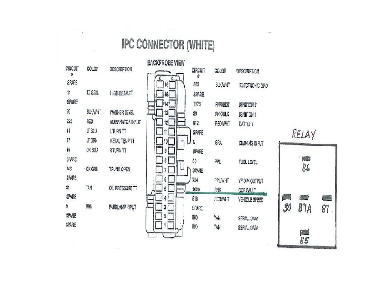
Per the GM TSB 00-03-11-001 (August 2000), vehicles with the 4.9L V8 engine. A modification of wiring harshness and installation of relay required to the control module for the suspension. The relay is a standard automotive 12-volt item and standard blade crimp connectors (obtained at an automotive supply store). Or you can obtain GM p/n 12193601 relay and p/n 15306045 connector. The Control Module location varies between models. Cadillac Eldorado: In trunk area attached to package shelf area or rear seat support. Cadillac Seville/SLS: In trunk area behind access panel attached to the rear seat support
- Locate and cut circuit 1020 (pink wire).
- Attach the instrument panel cluster (IPC) side of the circuit 1020 to pin 4 (87A) of the relay.
- Attach the module side of the circuit 1020 to pin 1 (86) of the relay.
- Attach a ground wire to pin 3 (30) of the relay.
- Attach a wire from a switched ignition source (which is 12V hot in Run) to pin 2 (85) of the relay.
This attachment will complete the circuit and resistance from the relay coil will be energized.
1991-1993 Cadillac Deville (with Computer Command Ride or CCR):
Per the GM TSB 00-03-11-001 (August 2000) and Service Manual page 8A-43-0. Modification of wiring harshness and installation of relay required to the control module for the suspension. The Control Module location varies between models.
Cadillac Deville: In trunk area behind the right hand side trim panel or on right side of rear seat support front trim panel. Locate and cut circuit 1300 (dark green wire) at the control module (pin CIS)
- This will disable the indicator lamp.
- Tape wires back into harness to prevent shorting to other components.
1994-1995 Cadillac Deville (with Speed Sensitive Suspension or SSS)
1996 Cadillac Deville (with Speed Sensitive Suspension or SSS)
1994-1995 Cadillac Eldorado / ELS (with Speed Sensitive Suspension or SSS)
1994-1995 Cadillac Seville / SLS / STS (with Speed Sensitive Suspension or SSS):
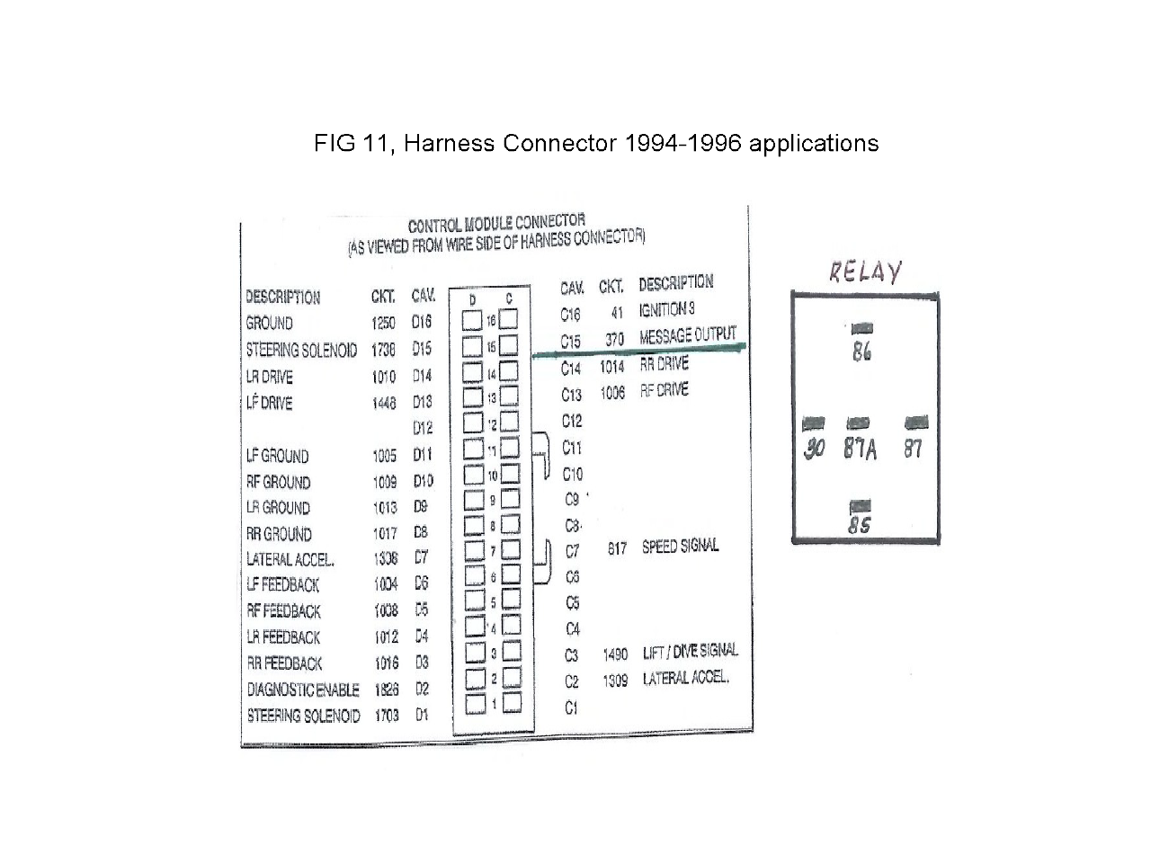
Per the GM TSB 00-03-11-001 (August 2000) and Service Manual page 8A-43-14, vehicles with the 4.9L V8 engine. A modification of wiring harshness and installation of relay required to the control module for the suspension. The relay is a standard automotive 12-volt item and standard blade crimp connectors (obtained at an automotive supply store). Or you can obtain GM p/n 12193601 relay and p/n 15306045 connector. The Control Module location varies between models. Cadillac Deville: In trunk area behind the right hand side trim panel or on right side of rear seat support front trim panel.
- Locate and cut circuit 370 (red wire).
- Attach the control module connector circuit 370 to pin 4 (87A) of the relay.
- Attach the module side of the circuit 370 to pin 1 (86) of the relay.
- Attach a ground wire to pin 3 (30) of the relay.
- Attach a wire from a switched ignition source (which is 12V hot in Run) to pin 2 (85) of the relay.
This attachment will complete the circuit and resistance from the relay coil will be energized.
This part of the procedure relates to disabling the warning systems for Air Compressor Pump Control. Not following this part of the instruction will lead to visual and/or audible warning signals or messages which will not harm the operation of the vehicle. The message or warning may cause annoyance after the conversion, but the suspension is fully operational. If needed, you can refer to the original equipment service manual for servicing the air leveling system using a scan tool. Several codes will detect air system is still functional or indicate items in question. This can reset any error codes for lights or message center to be illuminated.
- If conversion has been completed and no longer using onboard leveling compressor pump, this needs to be disabled. Locate the dedicated fuse within the fuse block; typically it is a 30 or 50 amp and remove to eliminate compressor pump operation.
- Refer to the owner’s manual or electrical circuit manual for location of fuse block for specific vehicle, either in the engine or trunk compartments.