For Vehicles:
- 2002-1997 Ford Expedition 2WD
- 2002-1997 Ford Expedition 4WD
- 2002-1997 Lincoln Navigator 2WD
- 2002-1997 Lincoln Navigator 4WD
- Read this instruction sheet and any instructions printed on the parts package carefully prior to removing the components from the vehicle.
- Do not grip the polished piston rod of a shock with any tool. Nicks or scratches will reduce the shock absorber’s service life.
- Part number on the shock or spring may differ from the part number on the carton. Contents are correct for the vehicle.
WARNING!
- Before servicing any vehicles equipped with original air spring suspension, turn off the “air suspension switch” located above the passenger side front kick panel or under the dash below the glove box.
- Do not attempt to remove the air spring from the suspension if it still contains air. Clear the air from the spring before servicing.
- If the shocks supplied are nitrogen gas pressurized, do not heat or open.
- Always wear safety glasses for eye protection.
- Use safety stands whenever a procedure requires you to be under a vehicle.
This kit replaces the rear air springs on the vehicles listed above. It will disable the air spring system and replace it with conventional variable rate coil springs. The kit is designed to provide a complete and thorough conversion of the suspension – as well as disengage the pump system. This system conversion kit also includes the necessary instructions to eliminate electronic warning signals.
Components in this kit are designed to replace worn or nonoperational original equipment parts on the vehicle, providing a conversion from air spring to conventional coil spring suspension.
This kit may be used for replacement on vehicles equipped with coil spring suspension, which is standard equipment on certain models.
If the air springs have failed, but the air pump is still functional, replacement air springs are available using alternate kits which will not disable the air system.
If needed, you can refer to the original equipment service manual for servicing the air spring air solenoid valves and for removal of the particular shock absorbers. This Instruction Sheet is a guideline and reference tool for the installation. Due to minor installation difficulty, it is necessary to follow the steps and methods detailed to ensure quality completion.
Some of the installation steps may require the use of special tools designed for specific procedures. The following tools and supplies are recommended for proper installation of this system:
- Ford Service Manual
- Torque Wrench (100 ft-lbs)
- Hydraulic Floor Jack
- Heavy Duty Floor Jack Stand
- Assorted ½” Drive Ratchet and Sockets
- Assorted Combination Wrenches
- Safety Glasses/Stands
Inspect all original parts as you remove them from the cartons for correct quantity and any potential damage. Obtain replacements where necessary.
- Prior to lifting the vehicle and removing its wheels, turn off the air suspension control switch, located above the passenger side front kick panel or under the dash below the glove box. Make sure that the ignition switch is in the OFF position.
- Raise vehicle at proper lift points. (Consult Ford Owners Manual if necessary) and make sure the vehicle is properly supported. Support the axle with a hoist or adjustable lift/stands.
- Locate the shock absorber on the suspension. Remove the shock absorber upper mounting stem components. Disconnect the air line from the shock by pushing on the colored outer ring (green or orange) and pulling on the tubing simultaneously. Disconnect the electronic connector (plastic). The female portion on the vehicle will not be reused. It is not necessary, should be placed in a poly bag and sealed with electrical tape to keep moisture out – for use if the air system is ever to be reinstalled.
- Remove the lower mounting bolts and save for reuse. Lower axle slightly to allow for removal, be sure you do NOT stretch brake lines or sensor wires.
- Install the new shock absorber, which has an outer coil spring to provide leveling, on the vehicle. Use the provided new upper cushion parts package; tighten to 23-28 ft-lbs (31 -38 N-m).
- Attach the lower mounting using the original bolt (replace if necessary). Tighten to 70-75 ft-lbs (95-101 N-m).
- Remove supports or jack stands. Upon completion, reinstall tires if removed and lower vehicle.
- Prior to lifting the vehicle and removing its wheels, turn off the air suspension control switch, located above the passenger side front kick panel or under the dash below the glove box. Make sure that the ignition switch is in the OFF position.
- Raise vehicle at proper lift points. (Consult Ford Owners Manual if necessary) and make sure the vehicle is properly supported.
- Support the axle with a hoist or adjustable lift/stands. Remove the shock absorber lower mounting bolts and save for reuse (if necessary). Lower axle slightly – approximately 1 inch. Be sure you do NOT stretch brake lines or sensor wires. Disconnect the lower end of the stabilizer links to provide addition clearance. Save nuts for reuse.
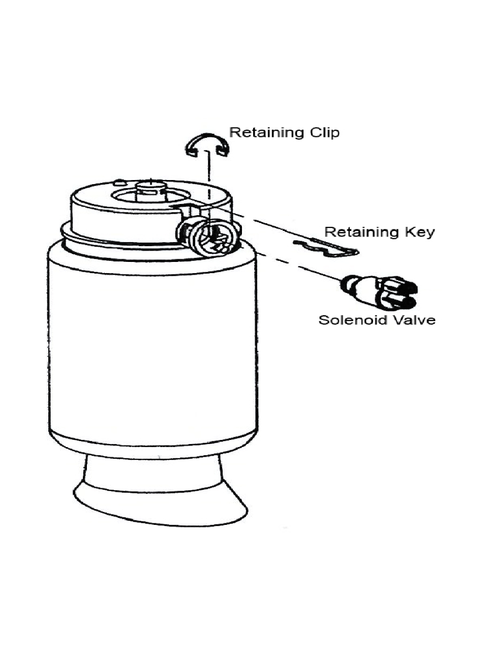
- (FIG. 1 below) Disconnect the electrical connector at the top of the spring. The air line is removed by pushing on the small colored outer ring and pulling on the line simultaneously. To release the air from the air springs, remove clip from solenoid clip and rotate the solenoid valves counter-clockwise to the first stop. This will allow the air in the spring and system to slowly escape. (Consult Ford Owners Manual if necessary).
- Rotate the solenoid valve to the second stop and the air will escape quickly. All air must be bled from system before removing solenoid. Rotate the solenoid to the third stop. The solenoid valve can be then be removed from the air spring housing. The line and connector should be placed in a poly bag and sealed with electrical tape to keep moisture out – for use if the air system is ever to be reinstalled.
- After the solenoid valves have been removed and all air has escaped, lower axle down to remove the air springs. Again, caution should be used to avoid stretching or bending brake lines/hoses or ABS sensor wires. It may be necessary to remove brake line bracket attachments to provide additional relief.
- Remove the spring retainer clip at the top of the air spring, above the upper spring seat. Then pry up on the lower portion of the air spring which has a retainer within the axle spring pilot. If this retainer happens to break off the air spring, there is no issue, however this item must be removed from the axle pilot and discarded. This will now permit removal of the air springs from the vehicle Note: Provided the solenoid valves and air springs are still functional, these should be retained if the air system is ever to be reinstalled.
- If replacing the shock absorbers, remove the upper stem attachment and remove from vehicle. Discard properly, using recommended recycling methods for this type of product.
- If replacing the shock absorbers, install upper mounting into the clevis and install bolt. Tighten to 70-75 ft-lbs (95-101 N-m).
- Install coil springs into the seat area in the upper pilot along with the isolator. Then position into the lower pilot. Note that spring does have a top and bottom, so install in the correct orientation. Repeat for both sides.
- Raise the axle assembly slightly after both springs are installed. Then reinstall the lower shock absorber mounting bolt and tighten to 70-75 ft-lbs (95-101 N-m).
- Reconnect the stabilizer link and tighten the nuts to 70-75 ft-lbs (95-101 N-m). Reconnect any brake line or ABS sensor wire brackets that were previously removed. Make sure the springs are secure and tight between the spring seats in the suspension.
This part of the procedure relates to disabling the warning systems for the Air Ride Suspension. Failure to follow this part of the instruction will lead to visual and/or audible warning signals. The signals will not harm the operation of the vehicle after the coil spring conversion, but may be an annoyance.
- Make sure engine is off and keys are not in the ignition.
- Ensure battery ground is disconnected.
- Turn OFF the air suspension switch located above the passenger side front kick panel or under dash below the glove box, if not previously done.
- Unplug the air pump connector C194 located behind the right hand head light near the air suspension pump and remove the fuse 15 within the power distribution box located at the left hand side of the vehicle.
- No additional items are to be completed with the Control Module, as this is required to maintain steering inputs to the EVO Steering Module.
- To disarm the “Check Air Suspension” light, remove the instrument cluster then unplug the light or remove the bulb from this warning lamp. Reinstall the instrument cluster.
- Turn back ON the air suspension switch located above the passenger side front kick panel or under dash below the glove box. This MUST be in the ON position to allow the EVO Steering to continue to function.