For Vehicles:
- 2005-1997 Buick Electra, LeSabre and Park Avenue
- 2010-2006 Buick Lucerne
- 1999-1995 Buick Riviera
- 2005-2000 Cadillac Deville
- 2004-1998 Cadillac Seville
- 2003-1995 Oldsmobile Aurora
- 2005-2000 Pontiac Bonneville
- Read this instruction sheet and any instructions printed on the parts package carefully prior to removing the components from the vehicle.
- Do not grip the polished piston rod of a shock with any tool. Nicks or scratches will reduce the shock absorber’s service life.
- Part number on shock or spring may differ from part number on carton. The contents are correct for the vehicle.
WARNING!
- Before servicing these vehicles equipped with original air leveling shocks, turn off the “air suspension switch” or “remove the power source (fuse) to the air pump.”
- Do not attempt to remove the air shock from the suspension if it still contains air. Clear the air from the spring before servicing.
- If the shocks supplied are nitrogen gas pressurized, do not heat or open.
- Always wear safety glasses for eye protection.
- Use safety stands whenever a procedure requires you to be under a vehicle.
This kit replaces the rear air shocks on the vehicles listed above. It will disable the air leveling feature system and replace it with conventional shock with assist coil springs. The kit is designed to provide a complete and thorough conversion of the suspension - as well as disengage the pump system. This system conversion kit also includes the necessary instructions to eliminate electronic warning signals.
Components in this kit are designed to replace worn or non-operational original equipment parts on the vehicle, providing a conversion from air leveling shock to a conventional shock with assist coil spring.
If the air shocks have failed, but the air pump is still functional, there are replacement air shocks are available. Using replacement air shocks will not disable the air system.
If needed, you can refer to the original equipment service manual for servicing the air leveling system using a scan tool. Several codes will detect air system is still functional or indicate items in question. The scan tool can also reset any error codes causing message lights or message center to be illuminated. This Instruction Sheet is a guideline and reference tool for the installation. Due to minor installation difficulty, it is necessary to follow the steps and methods detailed to ensure quality completion.
Some of the installation steps may require the use of special tools designed for specific procedures. The following tools and supplies are recommended for proper installation of this system:
- General Motors Service Manual
- Torque Wrench (100 ft-lbs)
- Hydraulic Floor Jack
- Heavy Duty Floor Jack Stand
- Assorted 1/2" Drive Ratchet and Sockets
- Assorted Combination Wrenches
- Safety Glasses/Stands
Inspect all original parts as you remove them from the cartons for correct quantity and any potential damage. Obtain replacements where necessary.
- Prior to lifting the vehicle and removing its wheels, turn off the air suspension control switch or remove the power source to pump (remove fuse). The pump electrical connection can be disconnected at the pump which is located behind the right rear fender well. A panel will need to be removed to gain access.
- Raise vehicle at proper lift points and rear wheels. (Consult GM Owners Manual if necessary) and make sure the vehicle is properly supported. Be sure to support the axle and be able to lower the wheel and tire on each side after the upper shock mounting is disconnected.
- Locate the shock upper mount behind the trunk side trim panels. Remove the two nuts that hold the upper mounting to the body panel. Do not remove the center nut which attaches shock stem to mount. Discard nuts, as new ones are supplied.
- Lower the supported axle to extend the shock. Disconnect the air line by spreading the clip, then pull the line free from the shock.
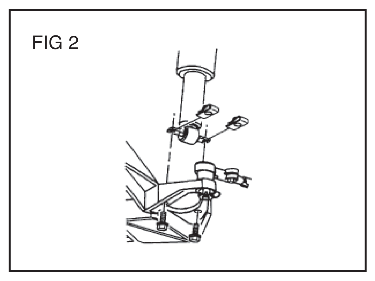
- Remove the two bolts from the lower mounting. The threaded clips on the cross pins are not needed for reinstallation. A new nut and bolt are provided for reattachment. Slightly compress the shock and remove.
- The air fitting should placed in a poly bag and sealed with electrical tape to keep moisture out - and tucked under the body out of way from the shock area or tire. This is only maintained for use if the air system is ever to be reinstalled.
- The shock absorbers provided for this conversion have a coil spring to maintain a similar vehicle height. Once installed, the vehicle may be up to 1/2" higher than original, dependent upon the model of the vehicle. Some settling will occur after time.
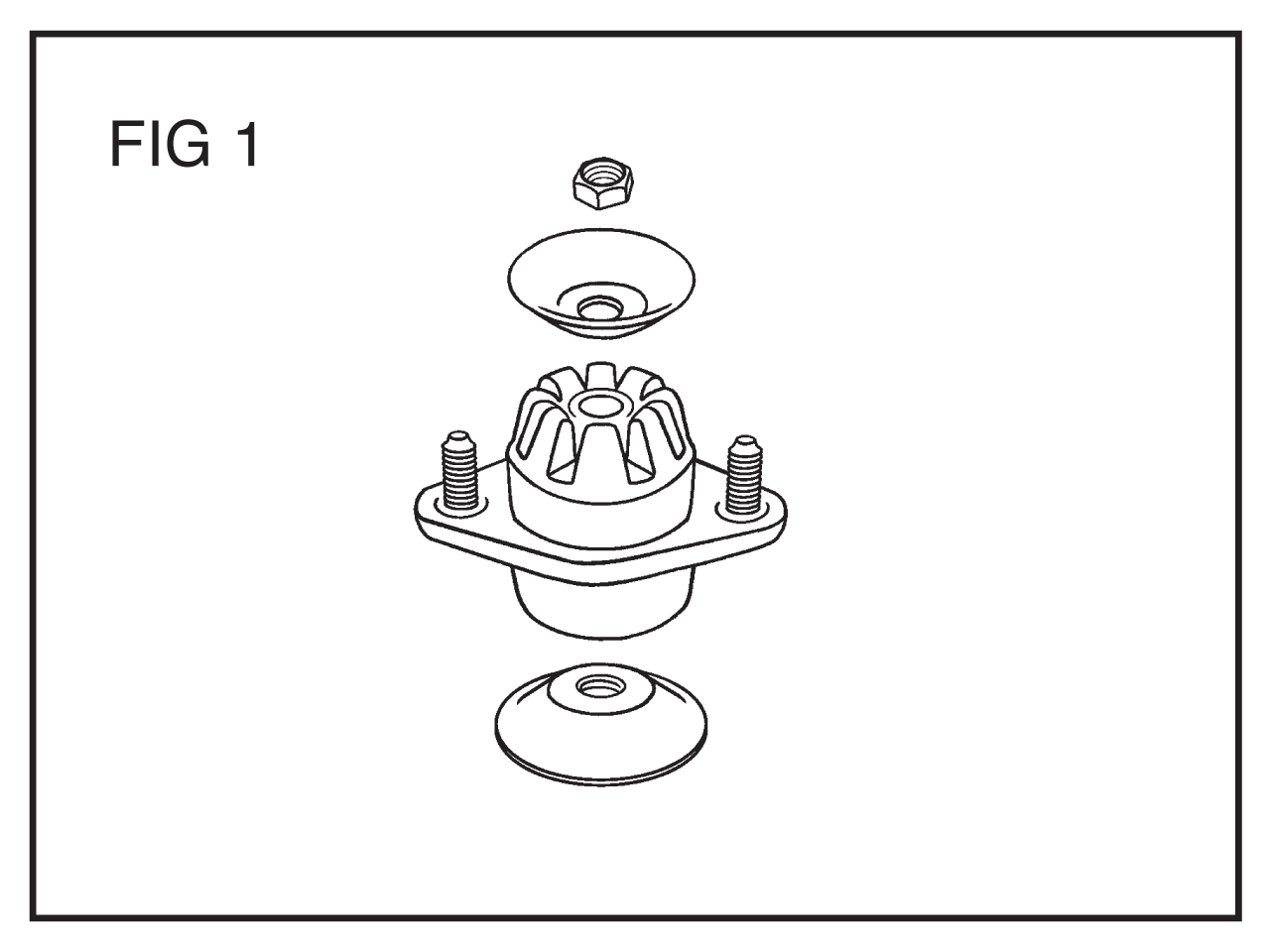
- Install the new upper mounting on to the stem mounting attachment. The stack order is: larger dished retainer, mount (with the two studs up), smaller dished retainer and then nut. Tighten to 24-28 ft-lbs (32-38 N-m).
- Install shock absorber into vehicle, aligning the upper mounting in the two holes. This mount does have an orientation. Attach the two upper mounting nuts inside the trunk - these will be tightened later.
- Align the lower mounting within the control arm. Line up the cross pin holes over the holes in control arm, then install the new bolts and nuts provided. The original clips do not need to be reused. The original bolts are excessively long because of OE production line installation requirements.
- Reinstall the tire and lower the vehicle removing all supports. Tighten the lug to 70 ft-lbs (94 N-m).
- After the vehicle is at static height (weight on ground), tighten the two upper mounting nuts to 15-18 ft-lbs (20-24 N-m).
This part of the procedure relates to disabling the pump leveling portion of the system and the warning indicators for the Automatic Leveling Control. Failure to follow this part of the instruction will only lead to the pump to continue to operate and visual and/or audible warning signals. The signals will not harm the operation of the vehicle after the conversion, but may be an annoyance.
- Disconnection of the pump:
- The pump should be electrically disconnected. Removal of only the fuse to this circuit is possible, but some vehicles have other items contained on this circuit.
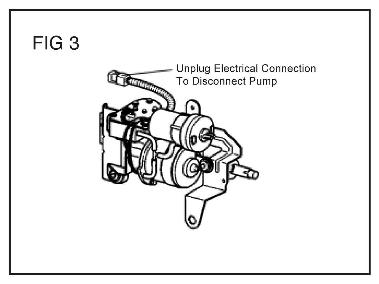
- Disconnection should be done at the pump, located behind the right rear wheel underbody. Remove the splash shield to gain access.
- Disconnect the two wire plug to eliminate electrical input. The wires connectors should be taped to protect from contamination, if reuse is desired. This is provided the pump is still operational.
- Reinstall any splash shields removed.
- Disabling of message or warning signal:
- For a temporary message center disable method:
- Some vehicles have a RESET button on the dash to reset the message center. This will only eliminate the message during the individual start cycle. It may have to be reset each time the vehicle is started or key is turned to on position.
- For a permanent message center disable method:
- This will require the control module to be disabled, using a Diagnostic System Scan tool to interface with the Rear Integrated Module (RIM). Connect to the class 2 serial data circuit.
- Make sure the ignition is ON, but with the engine OFF.
- Enter the appropriate vehicle information into the system to develop message output. Information pertaining to fault codes should be present once the suspension information has been found. Depending on the scan tool, different techniques to gain this information will be required. Follow the information guidelines for the particular device.
- If you receive a diagnostic message starting with a “U”, this particular instrument is not communicating with the system.
- Once the error codes have been achieved, these codes can be erased, which should eliminate the message values.
- For a temporary message center disable method: