For Vehicles:
- 1994-1988 Lincoln Continental
- Read this instruction sheet and any instructions printed on the parts package carefully prior to removing the components from the vehicle.
- Do not grip polished piston rod with any tool. Nicks or scratches will cause decreased service life.
- Part number on unit may differ from part number on carton. The unit is correct for the vehicle.
WARNING!
- If this unit is gas pressurized, do not heat or open.
- Always wear safety glasses for eye protection.
- Use safety stands whenever a procedure requires you to be under a vehicle.
This kit REPLACES all four air-suspension struts used on Lincoln Continentals from 1988 to 1994. WARNING: PARTIAL CONVERSION OF THE VEHICLE WILL LEAD TO DANGEROUS DRIVING CONDITIONS. This kit is designed to provide a complete and thorough conversion of the suspension structure. This system will not interfere with the vehicles other Electronic Control Unit’s, and it will not drain the electronics. It is necessary that these instructions be followed to insure that no electronic warning signals result.
It is recommended that an original equipment service manual be obtained prior to replacing these particular dampers. This Instruction Sheet is a guideline and reference tool for the installation of the coil spring units. Due to the difficulty of this installation, it is necessary to follow the steps and methods detailed to ensure quality completion.
Some of the service procedures require the use of special tools designed for specific procedures. The following tools and supplies are recommended for proper installation of this system:
- Ford Service Manual.
- Spring Compressor.
- Ford Tool: Torsion Spring Remover T88P-5310-A.
- Torque Wrench (200 ft-lbs.).
- Hydraulic Floor Jack.
- Heavy Duty Floor Jack Stands.
- Hammer.
- Mallet.
- Silicone Spray Lubricant.
- Assorted 1/2" Drive Ratchet and Sockets.
- Assorted Combination Wrenches.
- Safety Glasses/Stands.
Inspect all original parts as removed from the cartons for correct quantity and damage. Obtain replacements when necessary.
LE99001 - Front, Right Strut Box
| Part Number | Description | Quantity |
|---|---|---|
| LE30136 | Strut, Right | 1 |
| 118700004 | Coil Spring | 1 |
| 901926MM | Strut-Mate (Bearing Plate) | 1 |
| 130600040 | Upper Spring Seat | 1 |
| 63621MM | Boot & Bumper Kit | 1 |
| 160300006 | Lower Spring Isolator (small) | 1 |
LE99002 - Front, Left Strut Box
| Part Number | Description | Quantity |
|---|---|---|
| LE30137 | Strut, Left | 1 |
| 118700004 | Coil Spring | 1 |
| 901926MM | Strut-Mate (Bearing Plate) | 1 |
| 130600040 | Upper Spring Seat | 1 |
| 63621MM | Boot & Bumper Kit | 1 |
| 160300006 | Lower Spring Isolator (small) | 1 |
| P01291 | Parts Package | 1 |
LE99101 - Rear Strut Boxes (Quantity contained in 2 boxes)
| Part Number | Description | Quantity |
|---|---|---|
| LE30138 | Strut, Rear | 2 |
| 118700005 | Coil Spring | 2 |
| 902997MM | Strut-Mate (Bearing Plate) | 2 |
| 63621MM | Boot & bumper kit | 2 |
| 160300007 | LOWER SPRING ISOLATOR (large) | 2 |
| P01290 | parts package | 2 |
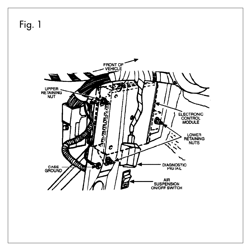
- Prior to lifting vehicle and removing wheels, turn off air suspension control switch, which is located on the left hand side of the luggage compartment in the trunk. Turn the ignition switch to the OFF position.
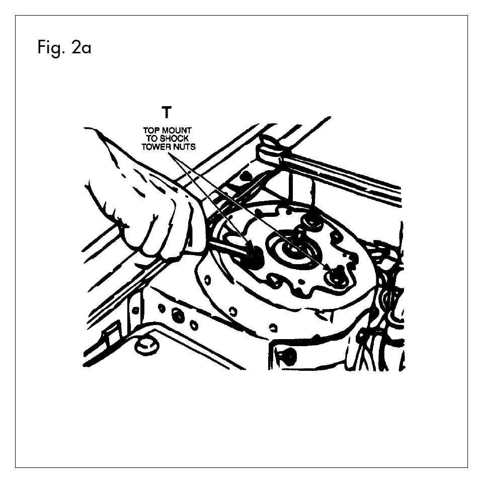
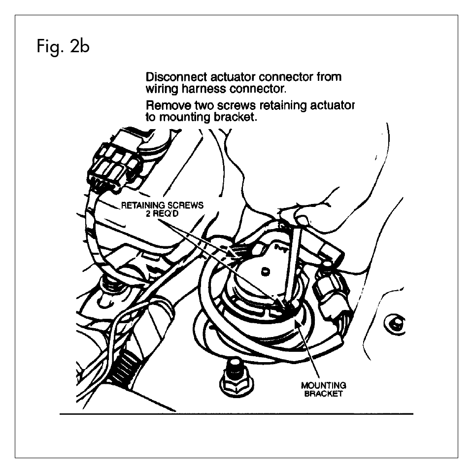
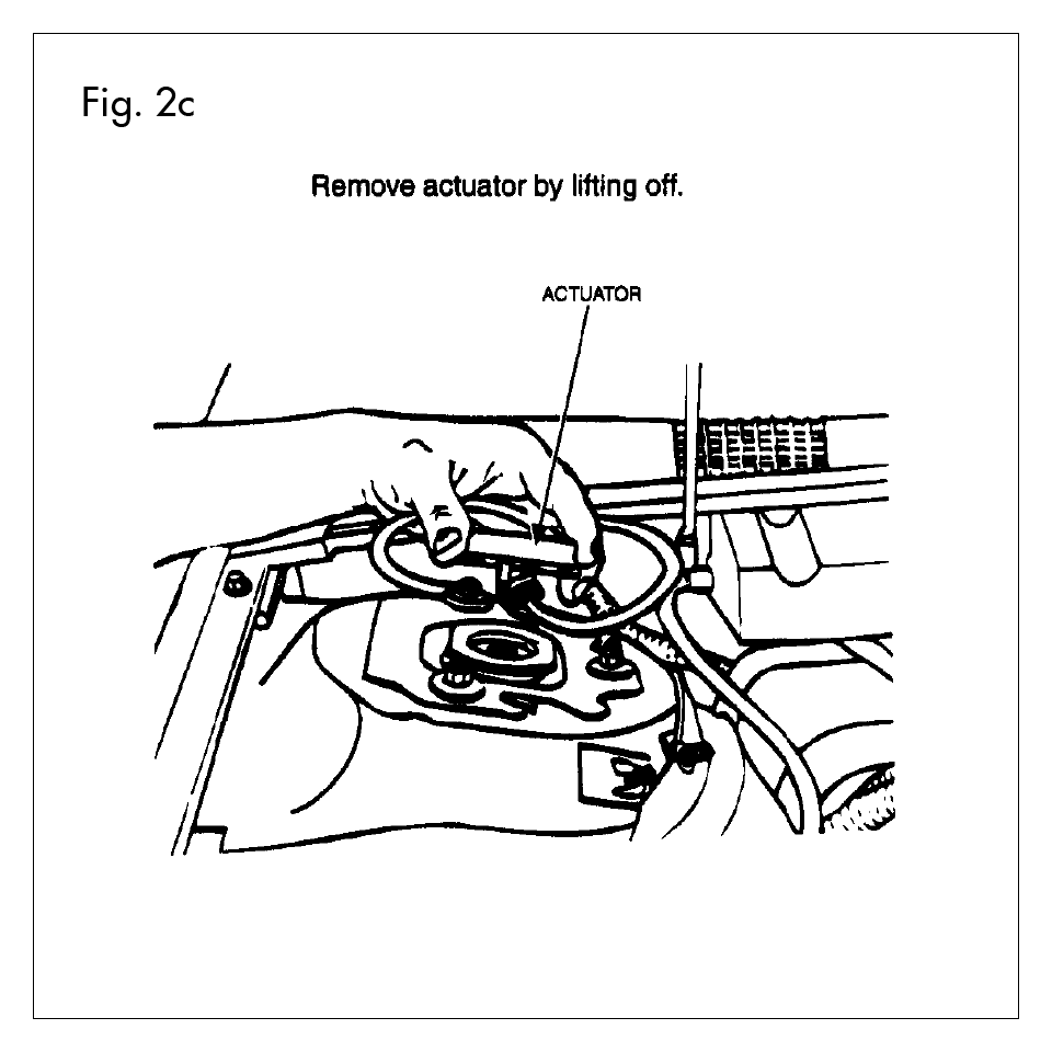
- (FIG. 2a, 2b and 2c) Remove plastic cover from shock tower to expose upper Tower Nuts (T) and strut actuator. Place aside. Loosen but do not remove the three upper Tower Nuts (T) at this time. Remove the Actuator wire from harness and remove two retaining screws. (FIG’s. 2b and 2c).
- Raise vehicle at proper lift points and remove wheels. (Consult Ford Owners Manual). CAUTION: Make sure the vehicle is proper supported.
- Move the ABS Sensor aside and away from any possible damage to the wire. Disconnect the Stabilizer Bar Link and inspect for wear. If necessary, obtain replacement part.
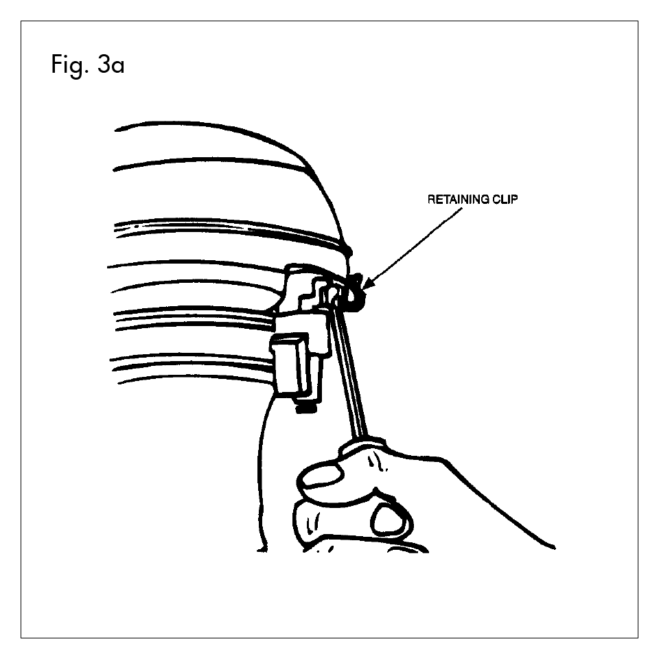
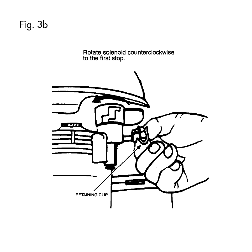
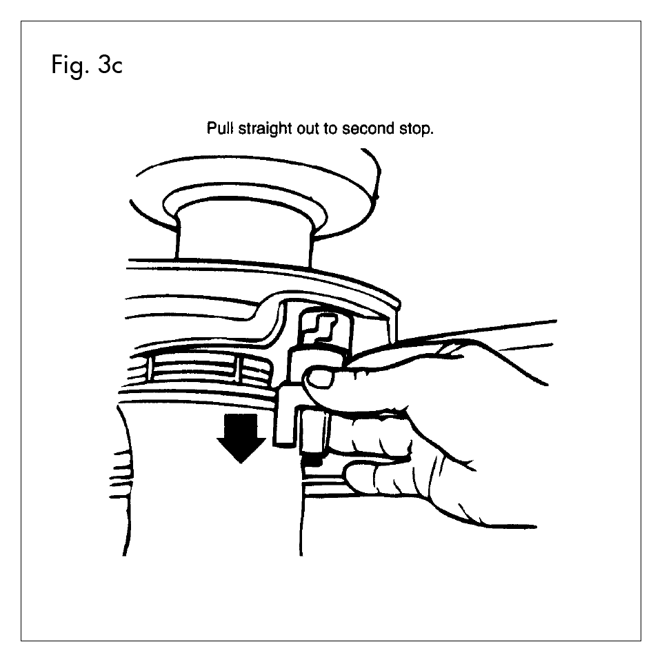
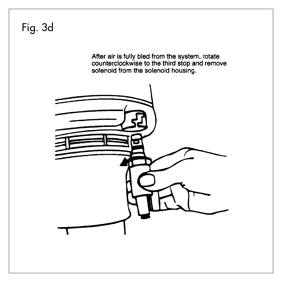
- (FIG. 3a, 3b, 3c and 3d) CAUTION: All air must be bled from strut before removing solenoid. Remove the electrical wire and clip from solenoid valve. Remove air line from valve. Remove the solenoid valve from strut by rotating counterclockwise to the first step. Some air will come out. Continue to rotate the solenoid valve to the second stop, and the air will exhaust quickly. Rotate the solenoid valve to the third stop, and remove the solenoid from the housing.
- After the solenoid valve has been disconnected, remove Pinch Bolt (P) from the strut spindle mounting at lower end. Using a blade screwdriver, slightly spread the knuckle pinch bolt joint to remove strut. Push down on lower assembly and compress strut (move upward) to separate. Once the strut is separated, remove the three Tower Nuts (T). Remove strut/air spring assembly from vehicle. Partially lower vehicle.
- If necessary, mark one of the upper mounting studs (K) on the new Upper Mount (in box LE99001 or LE99002) in relationship to the body for proper installation.
This part of the conversion is intended as a guideline to safeguard the electrical connectors for future reuse.
- Front:
- Verify that the actuators and solenoids are disconnected from vehicle.
- Pull air lines and unused electrical lines into the engine compartment.
- Wrap wires and lines together in a loose bundle. Use the supplied wire tie-down to secure wires and line to existing wiring harness. CAUTION: Make sure the wires are away from all heat sources, rotating engine parts and steering components.
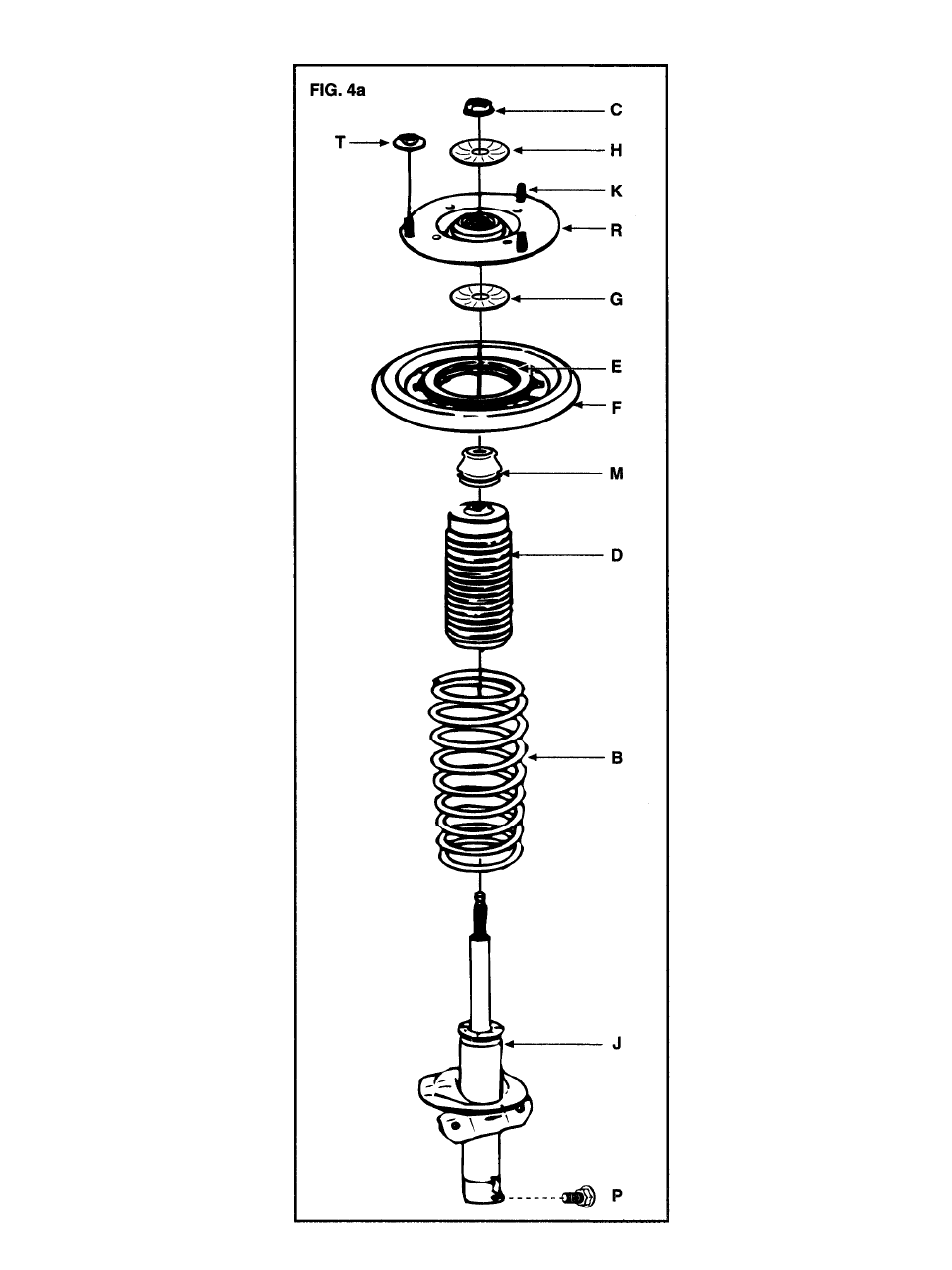
- Collect parts from the boxes labeled LE99001 Strut, Right and LE99002 Strut, Left. Carefully note the position and orientation of all parts to ensure proper assembly. CAUTION: Be sure that the correct assembly sequence and proper position of bearing and upper seat assembly are followed. The plastic tabs on the Upper Bearing (E) must snap into the metal spring seat (F) with a slight twisting motion. The lower (G) and upper (H) Mount Washers must be installed with proper orientation, “cup up” for both washers.
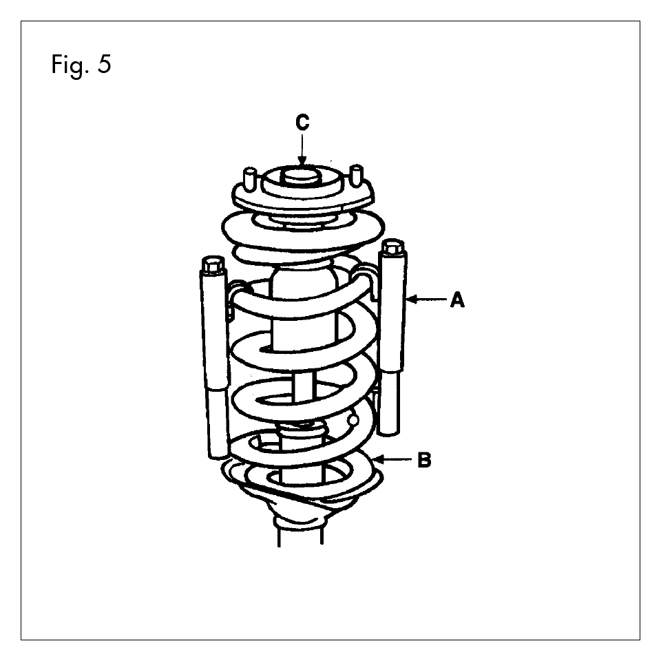
- Using a suitable spring compressing tool (A), compress spring (B) to an approximate height of 11.875 INCHES. This will ensure correct height before placement onto the strut assembly. CAUTION: Coil Spring is under compression load when installed. Attempts to install without properly restraining this load may result in injury.
- Install the Jounce Bumper (M) with Dirt Boot (D) on rod of each new unit.
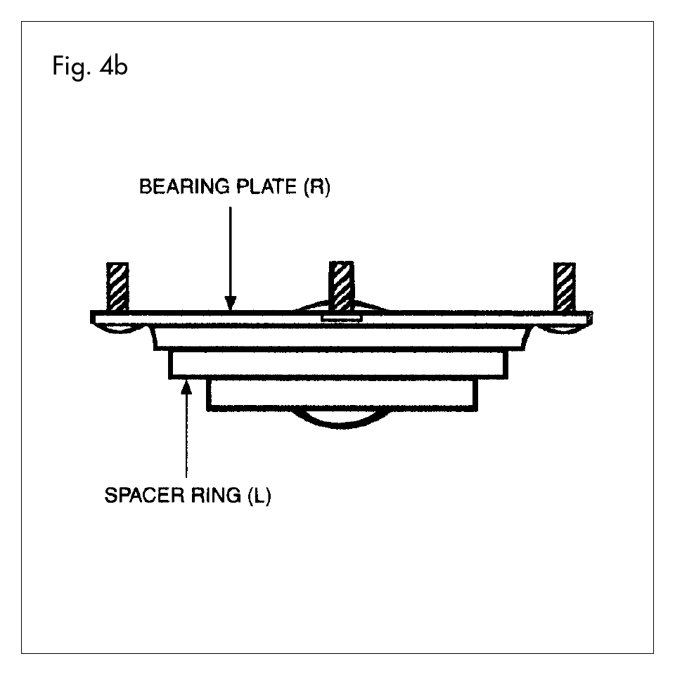
- Install Coil Spring Isolator (B), Upper Spring seat with Bearing ( in F), and Upper Strut Mount (R) with Strut (J). Be certain that Spring (B) is correctly seated in both the upper and lower spring seats. See FIG. 4b for Upper Strut Mount (R) assembly with Spacer Ring (L).
- Install new rod Lock-Nut (C) furnished and tighten to 35- 50 ft-lbs (48-68 N•m). CAUTION: Do not over tighten rod nut, excessive torque can damage the nut or the piston rod.
- Slowly remove the spring compressing tool (A).
- Install strut assembly at three upper mount-to-strut Tower Nuts (T) and tighten to 22-32 ft-lbs (30-43 N•m).
- Install strut damper strut-to-steering knuckle Pinch Bolt (P). Tighten to 70-95 ft-lbs (95-129 N•m). Obtain replacement bolt if the threads are bent or damaged. (Ref AK52).
- Install stabilizer bar link (replace if worn) to strut and install stabilizer bar link nut. Tighten to 55-75 ft-lbs (75-101 N•m). Replace front wheels.
- Prior to lifting vehicle and removing wheels, turn off air suspension control switch, which is located on the left hand side of the luggage compartment in the trunk. Turn the ignition switch to the OFF position.
- Remove necessary interior luggage compartment trim panels. In the luggage compartment, disconnect the electrical connection for the dual damping actuator. The actuator will be removed after the struts are removed from the vehicle.
- Loosen, but do not remove the three upper Tower Nuts (XT) at this time.
- Raise vehicle at proper lift points and remove wheels. Consult Ford Owners Manual. CAUTION: Make sure the vehicle is proper supported.
- (FIG. 3a, 3b, 3c and 3d) CAUTION: All air must be bled from strut before removing solenoid. Remove the electrical wire and clip from solenoid valve. Remove air line from valve. Remove the solenoid valve from strut by rotating counterclockwise to the first step. Some air will come out. Continue to rotate the solenoid valve to the second stop, and the air will exhaust quickly. Rotate the solenoid valve to the third stop, and remove the solenoid from the housing.
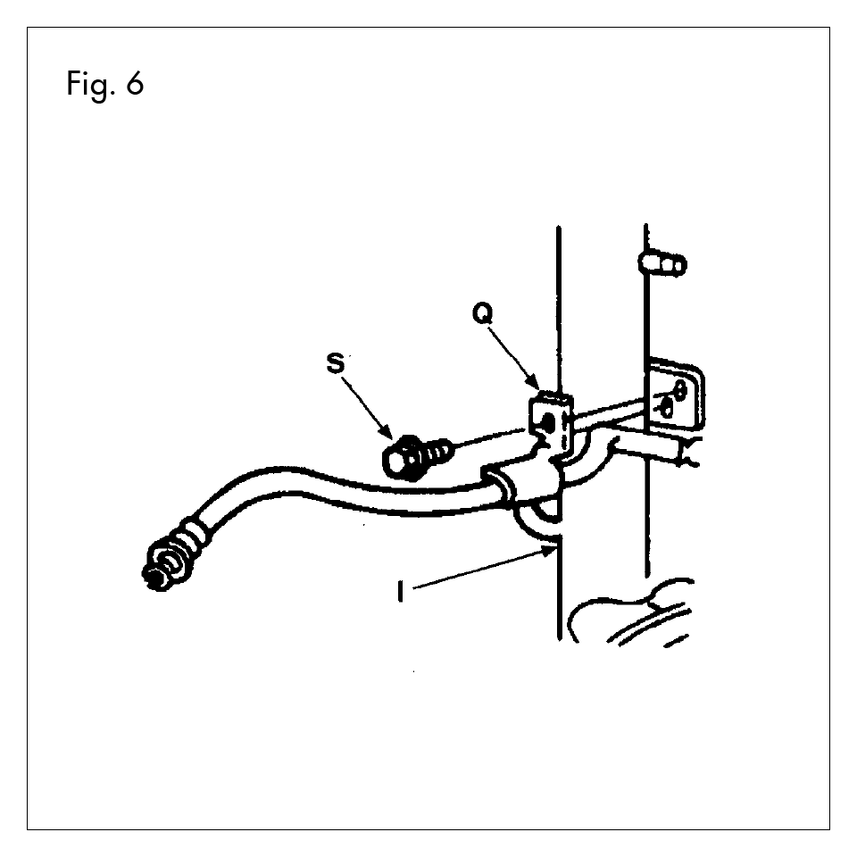
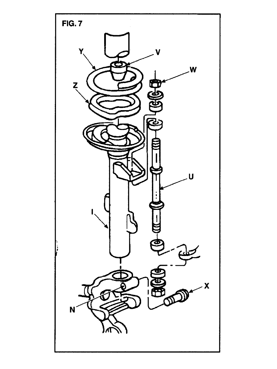
- (FIG. 6 and 7) Remove the brake line bracket (Q) and Stabilizer Bar Link (U) from the strut assembly. Remove the height sensor from the ball stud pin on the lower control arms. Save all for reuse.
- Special Removal Steps for the Rear Strut (FIG’s. 7 and 8).
- Remove torque spring clamp from strut body and 2 retainers on lower control arm.
- Use appropriate tool to relieve tension of lower torque arms.
- Remove torque spring and clamp form car.
- Remove nut, washer and insulator which retains the tension (forward link) to spindle mount.
- Remove lower bushing from spindle mount and move spindle rearward enough to separate rod from spindle.
- Remove Pinch Bolt (X) (FIG. 7) from strut spindle mount.
- Separate spindle mount from strut using a blade screwdriver to slightly spread the knuckle (N) and remove spindle/arm assembly.
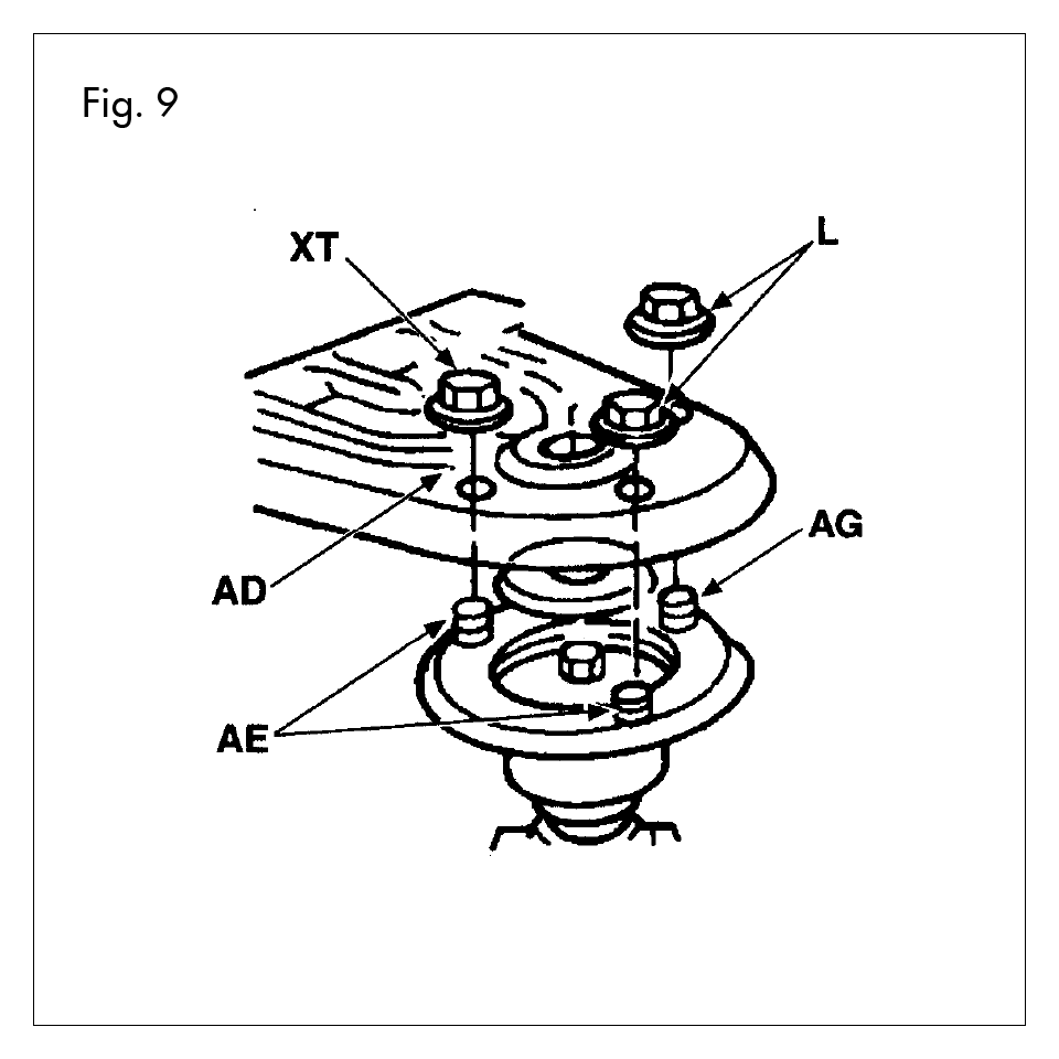
- Remove the three upper Tower Nuts (XT - FIG. 9). An assistant may be needed to help so that the strut/air spring assembly does not drop. Guide the electric actuator wire through the opening to prevent damage while removing strut assembly (I).
This part of the conversion is intended as a guideline to safeguard the electrical connectors for future reuse.
- Rear:
- Verify that the actuators and solenoids are disconnected from vehicle.
- Pull air lines and unused electrical lines into the tnink compartment.
- Wrap wires and lines together in a loose bundle. Use the supplied wire tie-down to secure wires and line to existing wiring harness.
- Use the supplied plugs to seal trunk.
- Reinstall interior of trunk.
- Inspect all original parts as removed for damage. Obtain replacements when necessary.
- Collect parts from the boxes labeled LE99101. Carefully note the position of all parts per FIG’s 5, 7, 8 and 9 to ensure proper assembly. CAUTION: Be sure that the correct assembly sequence and proper position of Upper Mount are followed.
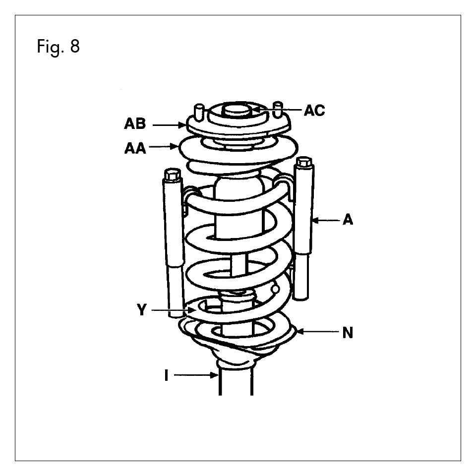
- Using a suitable spring compressing tool (A) compress rear Spring (Y) to approximately 11.375 inch length. CAUTION: Coil Spring AG is under compression load when installed. Attempts to install without properly restraining this load may result in injury.
- Install jounce bumper (V) with dirt boot on rod of new unit.
- (FIG. 7 & 8) Install Lower Spring Isolator (Z), Spring (Y), Upper Mount (AB) (Model years 1990-1994 require the reuse of the rubber Isolator, currently on the Air Strut. This Upper Isolator must be installed onto the studs of the Upper Mount (AB), before it is installed on the vehicle.) Be sure that the spring is correctly seated onto bottom spring seat. CAUTION: Verify orientation of bearing plate and strut. To check this upper mount and strut for proper orientation by comparing it with the air strut that was removed earlier. Or, position strut mount so that the pair of studs (approximately 4-3/8 inch apart) are on the same side as the stabilizer bracket on the strut. (Other stud pairs are approximately 5-1/16 inch apart).
- Install new Rod Nut (AC) provided and torque to 35-50 ft- lbs (47-69 N•m). Use 21mm box wrench to turn rod nut and 10mm crow’s foot wrench to hold shaft, so shaft will not turn while tightening rod nut. CAUTION: Do not over tighten rod nut, excessive torque can damage the nut or the piston rod.
- Make sure all reference marks per step 28 are aligned. Slowly release tension on the coil spring until fully seated. Remove spring compressing tool (A).
- Reattach Stabilizer Bar Link (U) to Strut assembly (I). Torque Nut (W) to 5-7 ft-lbs (7-9.5 N•m). Recommended to replace this link if worn or damaged.
- Install strut to vehicle by inserting upper retaining studs (AE & AG) into strut tower (AD) and hand-starting three upper Cushion Tower Nuts (XT). For model years 1990-1994, the Sleeves (AH) must be placed on the studs (AE and AG) BEFORE attaching the Tower Nuts.
- Partially raise vehicle.
- Install strut assembly (I) into spindle pinch joint (N). Push or tap spindle assembly (N) onto strut. Remove screwdriver from pinch joint opening.
- Install spindle-to-strut assembly pinch bolt (X) into spindle (N) and through Strut (I). Torque bolt (X) to 51-70 ft-lbs (68-95 N•m). NOTE: Obtain replacement bolt if the threads are bent or damaged. (Ref AK50). Install Stabilizer Bar Link into Stabilizer Bar and torque nut to 5-7 ft-lbs (7-9.5 N•m).
- Install brake hose bracket (Q) to strut assembly (I). Torque bolt (S) to 7-11 ft-lbs (9.5-15 N•m).
- Reattach height sensor and brake differential control valve to control.
- Install wheel and tire assembly and lower vehicle.
- Torque three upper Tower Nuts (XT) to 19-26 ft-lbs (26-35 N•m).
- Check alignment of entire vehicle after installation, and adjust as necessary.
This part of the procedure relates to the disabling the warning systems for the Air Ride Suspension. Failure to follow this part of the instruction will lead to visual and audible warnings signals.
- Make sure engine is off and keys are not in the ignition.
- Ensure battery ground is disconnected.
- On driver side of trunk, plug the Parts Package supplied connector into the Diagnostic Pigtail.
- Find any sheet metal screw close to the Diagnostic Pigtail and screw terminal with sheet metal screw.
- Ensure that the solderless connector is grounded.
- Please remove the fuse for the Air Suspension Motor (Cavity A, 40 amps, Green), located in the High- Current Fuse Panel, located on the drive-side of the engine compartment. CAUTION: It is recommended to disconnect the battery ground cable before removing the fuse.